Direct-current auxiliary power supply system

A power supply system and auxiliary power supply technology, applied in the field of rail transit, can solve the problems of harmonic pollution, increased loss, and lack of flexibility, and achieve the effect of avoiding AC voltage distortion, reducing power conversion links, and avoiding harmonic pollution.

Pending Publication Date: 2019-02-22
CHINA RAILWAYS CORPORATION +3
View PDF0 Cites 4 Cited by
  • Summary
  • Abstract
  • Description
  • Claims
  • Application Information

AI Technical Summary

Problems solved by technology

[0004] However, no matter what kind of auxiliary system in the prior art, since the charger mostly uses uncontrolled rectification to convert 380V AC into DC and then performs dc / dc conversion, on the one hand, there is an additional stage of rectification power conversion, which increases the loss. On the other hand, the uncontrolled rectification has brought harmonic pollution to the 380V AC busbar. In addition, it has become a trend to use frequency conversion air conditioning technology for rail vehicles. However, considering the cost factor, the front end of the frequency conversion air conditioner usually uses uncontrolled rectification. Therefore, Like the aforementioned charger, there are also problems of low efficiency and harmonic pollution, which limit the popularization and application of inverter air conditioners in rail vehicles
The structure of the current auxiliary system has limited room for improvement in the face of the urgent demand for energy saving and high efficiency, and the flexibility is also stretched

Method used


Image

  • Direct-current auxiliary power supply system
  • Direct-current auxiliary power supply system
  • Direct-current auxiliary power supply system

Examples


Embodiment Construction

[0046]In order to make the purpose, technical solutions and advantages of the embodiments of the present invention clearer, the technical solutions in the embodiments of the present invention will be clearly and completely described below in conjunction with the drawings in the embodiments of the present invention. Obviously, the described embodiments It is a part of embodiments of the present invention, but not all embodiments. Based on the embodiments of the present invention, all other embodiments obtained by persons of ordinary skill in the art without creative efforts fall within the protection scope of the present invention.

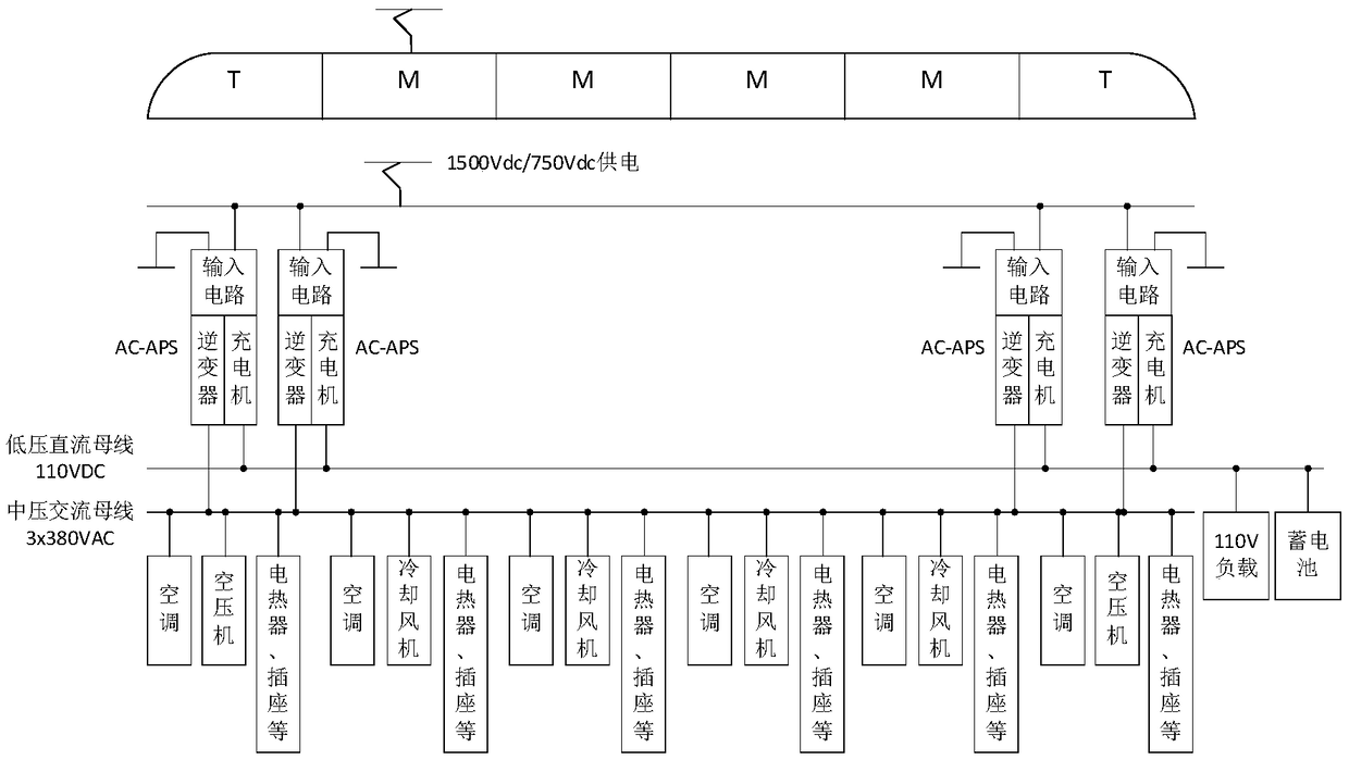
[0047] Considering the problems of inefficiency and harmonic pollution existing in the auxiliary systems of rail vehicles, the embodiment of the present application provides a method that can effectively reduce the link of electric energy conversion, reduce electric energy loss and improve the operating efficiency of auxiliary systems, and then can ...


PUM


Abstract

The invention provides a direct-current auxiliary power supply system. The direct-current auxiliary power supply system comprises a high-voltage direct-current bus, a medium-voltage direct-current bus, a low-voltage direct-current bus, a direct-current auxiliary converter and a direct-current charger, wherein the high-voltage direct-current bus, the medium-voltage direct-current bus and the low-voltage direct-current bus are arranged on a rail vehicle; the direct-current auxiliary converter is connected between the high-voltage direct-current bus and the medium-voltage direct-current bus; thedirect-current charger is connected between the medium-voltage direct-current bus and the low-voltage direct-current bus; the high-voltage direct-current bus is connected to a contact net or a third rail and is used for supplying power to a traction motor of the rail vehicle; the direct-current auxiliary converter is used for supplying power to the medium-voltage direct-current bus; the medium-voltage direct-current bus is used for supplying power to each medium-voltage load in the rail vehicle; the direct-current charger is used for supplying power to the low-voltage direct-current bus; eachmedium-voltage load comprises a frequency-variable air conditioner; and the low-voltage direct-current bus is used for supplying power to a 110V-level storage battery of the rail vehicle. The direct-current auxiliary power supply system provided by the invention can effectively reduce the procedures of conversion of electric energy, can reduce electric energy loss, can improve the running efficiency of an auxiliary system, can lower the running cost of the overall auxiliary system and can improve the energy saving effect of the auxiliary system.

Description

technical field [0001] The present application relates to the technical field of rail transit, in particular to a DC auxiliary power supply system. Background technique [0002] The traction-auxiliary system is an important on-board equipment of rail vehicles. The traction system uses the traction converter as the core device to provide traction power for the whole train; while the auxiliary system uses the auxiliary converter as the core to provide Provide AC power for three-phase loads and some single-phase loads such as train air conditioners, air compressors, and cooling fans. [0003] The auxiliary system of existing rail vehicles usually adopts a power frequency transformer isolation method. After the DC power is inverted into a three-phase AC power, the three-phase AC power is converted into a three-phase power frequency power output by the power frequency transformer. Since power frequency transformers are not conducive to weight reduction, an auxiliary converter wi...

Claims


Application Information

Patent Timeline
Patent Type & Authority Applications(China)
IPC IPC(8): B60L9/04B60M3/00B61C3/00
CPCB60L9/04B60L2200/26B60M3/00B61C3/00
Inventor 董侃马颖涛邱腾飞刘东辉宋术全赵震刘伟志李水昌杜玉亮刘冰杨宁祝文昭李旭阳朱雨桐
Owner CHINA RAILWAYS CORPORATION
Why Eureka
Try Eureka