
Intelligent energy-saving automatic control method of dust removal system in thermal power plant

A technology of dust removal system and thermal power plant, applied in power supply technology, electrostatic separation and other directions, can solve the problem of the high electricity consumption rate of electrostatic precipitator and wet electrostatic precipitator, and the inability to automatically adjust operating parameters and operation methods at any time. High operating power consumption to achieve the effect of ultra-low emission

Active Publication Date: 2019-02-22
HUANENG XINDIAN POWER GENERATION CO LTD +2
View PDF8 Cites 4 Cited by
  • Summary
  • Abstract
  • Description
  • Claims
  • Application Information

AI Technical Summary

Problems solved by technology

However, the unreasonable operation mode and operating parameters of the high-voltage power supply cause the high power consumption of the dust collector. The power consumption of these high-voltage power supplies accounts for more than 80% of the total power consumption of the entire dust removal system. When the parameters of the working conditions such as the quantity change, the operating parameters cannot be automatically adjusted at any time, which makes the power consumption rate of the electrostatic precipitator and wet electrostatic precipitator remain high

Method used


Image

  • Intelligent energy-saving automatic control method of dust removal system in thermal power plant
  • Intelligent energy-saving automatic control method of dust removal system in thermal power plant
  • Intelligent energy-saving automatic control method of dust removal system in thermal power plant

Examples


Embodiment Construction

[0019] The present invention is described in further detail below in conjunction with accompanying drawing:

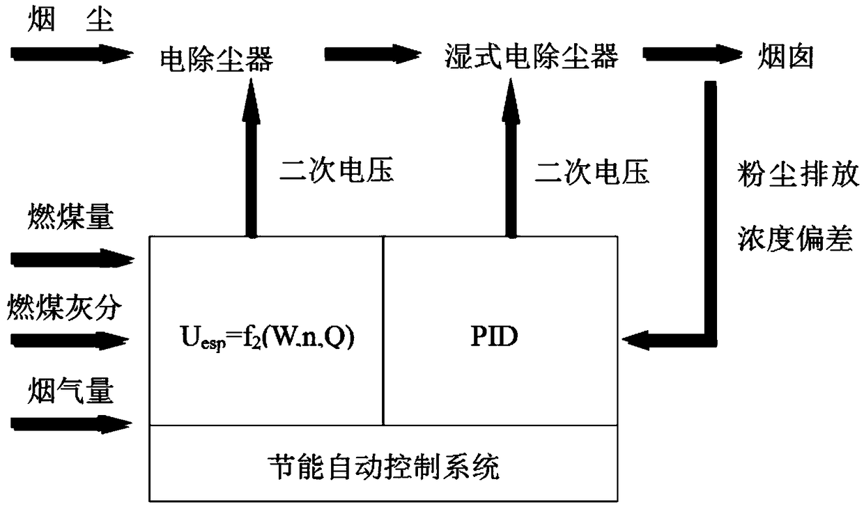
[0020] refer to figure 1 , the thermal power plant dust removal system intelligent energy-saving automatic control method comprises the following steps:

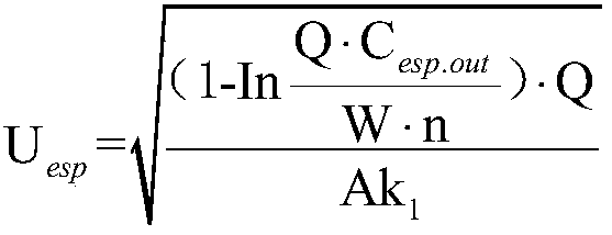
[0021] Real-time acquisition of unit coal consumption, coal combustion ash and flue gas volume, and then calculate the high-voltage power supply secondary voltage U of the electrostatic precipitator based on the unit coal combustion volume, coal combustion ash content and flue gas volume 电 The set value of U esp , and then according to the secondary voltage U of the high-voltage power supply of the electrostatic precipitator 电 The set value of U esp Adjust the secondary voltage U of the high-voltage power supply of the electrostatic precipitator through the DCS system 电 , where, the secondary voltage U of the high voltage power supply of the electrostatic precipitator 电 The set value of U esp The expression is:...


PUM


Abstract

The invention discloses an intelligent energy-saving automatic control method of a dust removal system in a thermal power plant. The method comprises the following steps that a coal combustion amount,a coal ash content and a flue gas quantity of a unit are acquired in real time, then according to the fire coal amount, fire coal ash content and smoke amount of the unit, a set value Uesp of a secondary voltage U-electricity of a high-voltage power supply of an electric dust remover is calculated, and then the secondary voltage U-electricity of the high-voltage power supply of the electric dustremover is adjusted according to the set value Uesp of a secondary voltage U-electricity of the high-voltage power supply of the electric dust remover; and the actual smoke dust emission concentrationof an outlet of a wet-type electric dust collector is measured in real time, then a set value Uwesp (n) of U-wet electricity of the secondary voltage of the high-voltage power supply of the wet-typeelectric dust remover is calculated according to the actual smoke dust emission concentration of the outlet of the wet-type electric dust remover through a PID mode, and then according to a set valueUwesp (n) of the secondary voltage U-wet-type electric dust collector of the high-voltage power supply of the wet electric dust remover, the secondary voltage U-wet-type electric dust collector of thehigh-voltage power supply of the wet-type electric dust remover is adjusted. According to the method, the high-voltage power supply of the electric dust remover and the high-voltage power supply of the wet electric dust remover can be efficiently and efficiently operated under different working conditions.

Description

technical field [0001] The invention belongs to the technical field of flue gas dust removal in coal-fired power plants, and relates to an intelligent energy-saving automatic control method for a dust removal system in a thermal power plant. Background technique [0002] According to the requirements of the National Development and Reform Commission, the Ministry of Environmental Protection, and the National Energy Administration in 2014, by the end of 2017, most coal-fired power plants had completed ultra-low emission transformation. Many power plants have upgraded the traditional high-voltage silicon rectifier power supply for electrostatic precipitators into advanced and efficient high-frequency power supplies and pulse power supplies. As a new type of dust removal equipment, the wet electrostatic precipitator is installed after the wet desulfurization device, and has also achieved large-scale application. Wet electrostatic precipitators generally use power frequency con...

Claims


Application Information

Patent Timeline
Patent Type & Authority Applications(China)
IPC IPC(8): B03C3/68
CPCB03C3/68
Inventor 刘增瑞白永岗张华东张超边明心李东阳李杰郭明
Owner HUANENG XINDIAN POWER GENERATION CO LTD
Learn More