A new type of intelligent agricultural spraying device
An intelligent and new technology, which is applied to the device for capturing or killing insects, animal husbandry, application, etc., can solve the problems of unable to bury fixed pesticides, unable to change the concentration ratio of pesticides, and incomplete spraying, etc., to achieve simple and reasonable structure, Pesticide concentration can be adjusted and the effect of reducing labor intensity
- Summary
- Abstract
- Description
- Claims
- Application Information
AI Technical Summary
Problems solved by technology
Method used
Image
Examples
Embodiment 1
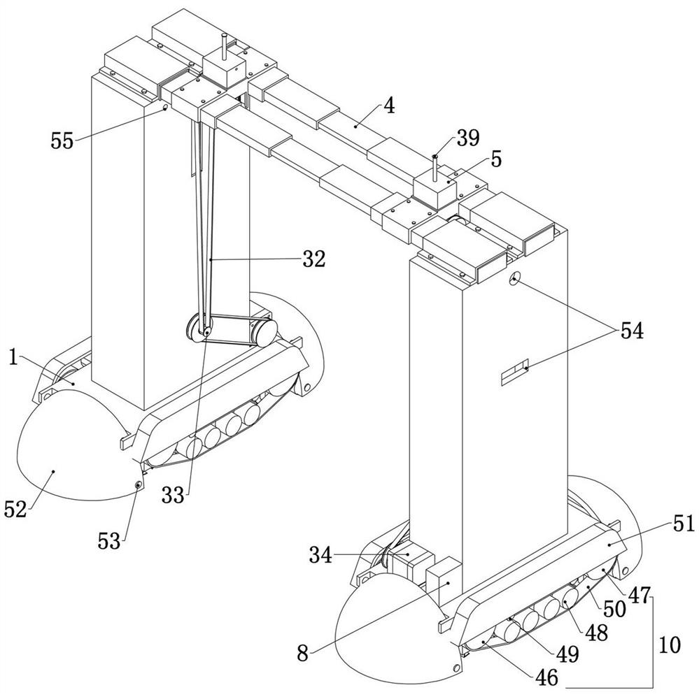
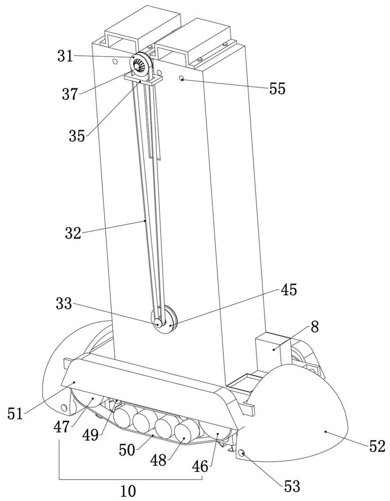
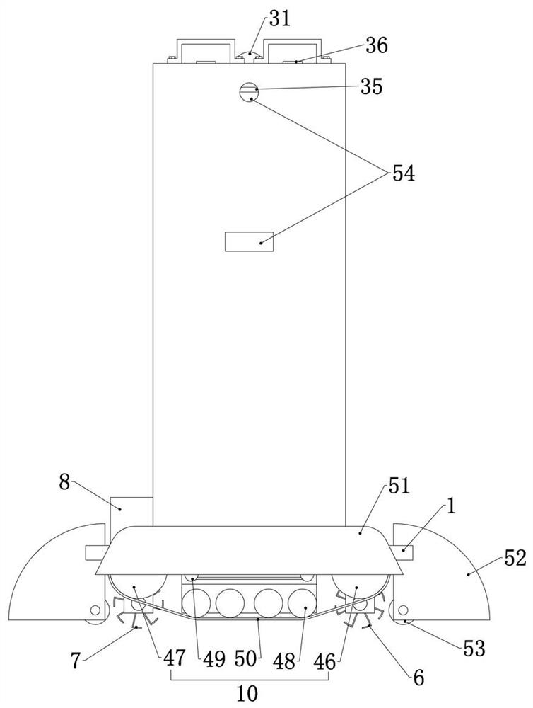
[0037] Embodiment 1, the present invention is a new type of intelligent agricultural spraying device, including two trolleys 1, the trolleys 1 walk in the field ridges in the field, and the trolleys 1 provide a fixed foundation for the follow-up structure at the same time, it is characterized in that the two trolleys Each of the trolleys 1 is provided with a spraying device, and the two spraying devices are fixedly connected with a silo 2, and the spraying device is used for spreading solid pesticides, and the solid pesticides in the silos 2 can be spread. In the field ridge, the upper ends of the two feed bins 2 are fixedly connected with water bins 3, and the two water bins 3 are equipped with water pressure devices, and the two water bins 3 are connected through telescopic nozzles 4. , the water pressure device can press the water in the water tank 3 into the telescopic nozzle 4 connected with it, and the telescopic nozzle 4 is a common telescopic water spray pipe, and there...
Embodiment 2
[0039] Embodiment 2. On the basis of Embodiment 1, this embodiment provides a specific stepless adjustment structure to achieve a stable output of water per unit time in the pressurized water device, and at the same time drive the drug discharge device to output different adjustable drug discharge volumes. Specifically, the stepless adjustment device includes an adjustment drive pulley 11 that is rotatably connected to the lower end surface of the medicine bin 5, and the adjustment drive pulley 11 is connected to the water pressure device, that is, the pressure water device The water device works and drives the driving pulley 11 to rotate, and the adjusting driving pulley 11 is connected to the adjusting driven pulley 12 connected to the lower end surface of the drug storehouse 5 through a belt, and the adjusting driven pulley 12 is connected with the The shaft is fixedly connected with a variable speed drive upper pulley 13, that is, the rotation of the adjustment drive pulley...
Embodiment 3
[0042] Embodiment 3, on the basis of Embodiment 2, this embodiment provides a specific structure for driving the synchronous sliding of the driving guide shaft 14 and the driven guide shaft 17, so as to realize the variable speed driving pulley 21 and the variable speed The synchronous change of the diameter of the driven pulley 22, specifically, the lower end of the drug storehouse 5 is fixedly connected with a fixed plate 24, refer to Figure 7 , Figure 8 , the fixed plate 24 is the fixed base of the stepless adjustment device, the driving guide shaft 14 and the driven guide shaft 17 are connected to the fixed plate 24 by sliding up and down through the fixed plate 24, the A variable speed drive gear 25 is rotatably connected to the fixed plate 24, and the variable speed drive gear 25 is driven by a variable speed drive motor 26 fixedly connected to the fixed plate 24. The variable speed drive motor 26 is a servo with constant output power. The name of the motor is only us...
PUM
 Abstract
Description
Claims
Application Information
 - R&D
- Intellectual Property
- Life Sciences
- Materials
- Tech Scout
- Unparalleled Data Quality
- Higher Quality Content
- 60% Fewer Hallucinations
Browse by: Latest US Patents, China's latest patents, Technical Efficacy Thesaurus, Application Domain, Technology Topic, Popular Technical Reports.
© 2025 PatSnap. All rights reserved.Legal|Privacy policy|Modern Slavery Act Transparency Statement|Sitemap|About US| Contact US: help@patsnap.com


