Clamp with controllable clamping force and for machining

A clamping force and fixture technology, applied in the direction of manufacturing tools, metal processing equipment, metal processing machinery parts, etc., can solve the problems of surface damage of aluminum products, noise from the use of cylinders, waste of resources, etc., to improve processing efficiency and avoid damage , The effect of good pressing force

Active Publication Date: 2019-02-19
江苏天氟隆防腐设备有限公司
View PDF15 Cites 5 Cited by
  • Summary
  • Abstract
  • Description
  • Claims
  • Application Information

AI Technical Summary

Problems solved by technology

[0003] Among the existing equipment, it is more commonly used to set vises on the workbench, or use cylinder clamps to clamp, and then process the workpiece. When using vises, it takes more time to clamp, but using cylinders When fixing, continuous air supply is required to maintain the stability of the cylinder, which will cause waste of resources, and the use of the cylinder in the workshop will cause a lot of noise, so it is necessary to design a fixture that can quickly and stably fix aluminum profiles
[0004] In addition, because the material of the aluminum profile is relatively soft, when positioning the workpiece, increasing the contact area between the force application surface and the surface of the workpiece, and at the same time making the pressure vertically applied to the surface of the workpiece can effectively ensure the compaction effect of the aluminum product. In addition, When the pressing force is large, it will cause certain damage to the surface of the aluminum product workpiece. Therefore, it is very important to design a fixture that is easy to adjust, adaptable to various workpieces, and can effectively control the clamping force. Necessary

Method used


Image

  • Clamp with controllable clamping force and for machining
  • Clamp with controllable clamping force and for machining
  • Clamp with controllable clamping force and for machining

Examples


Embodiment Construction

[0015] The specific implementation manners of the present invention will be described in further detail below in conjunction with the accompanying drawings.

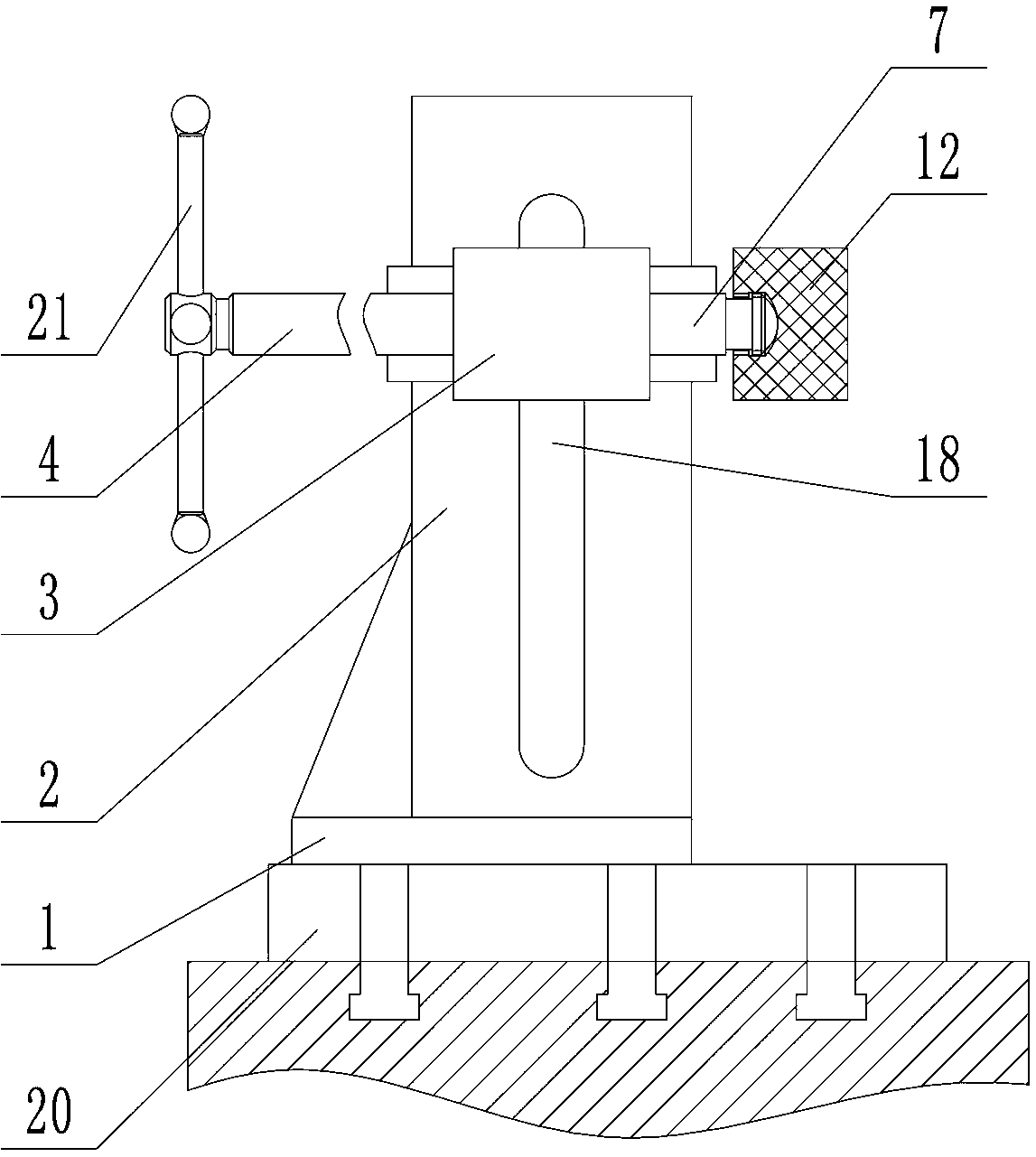
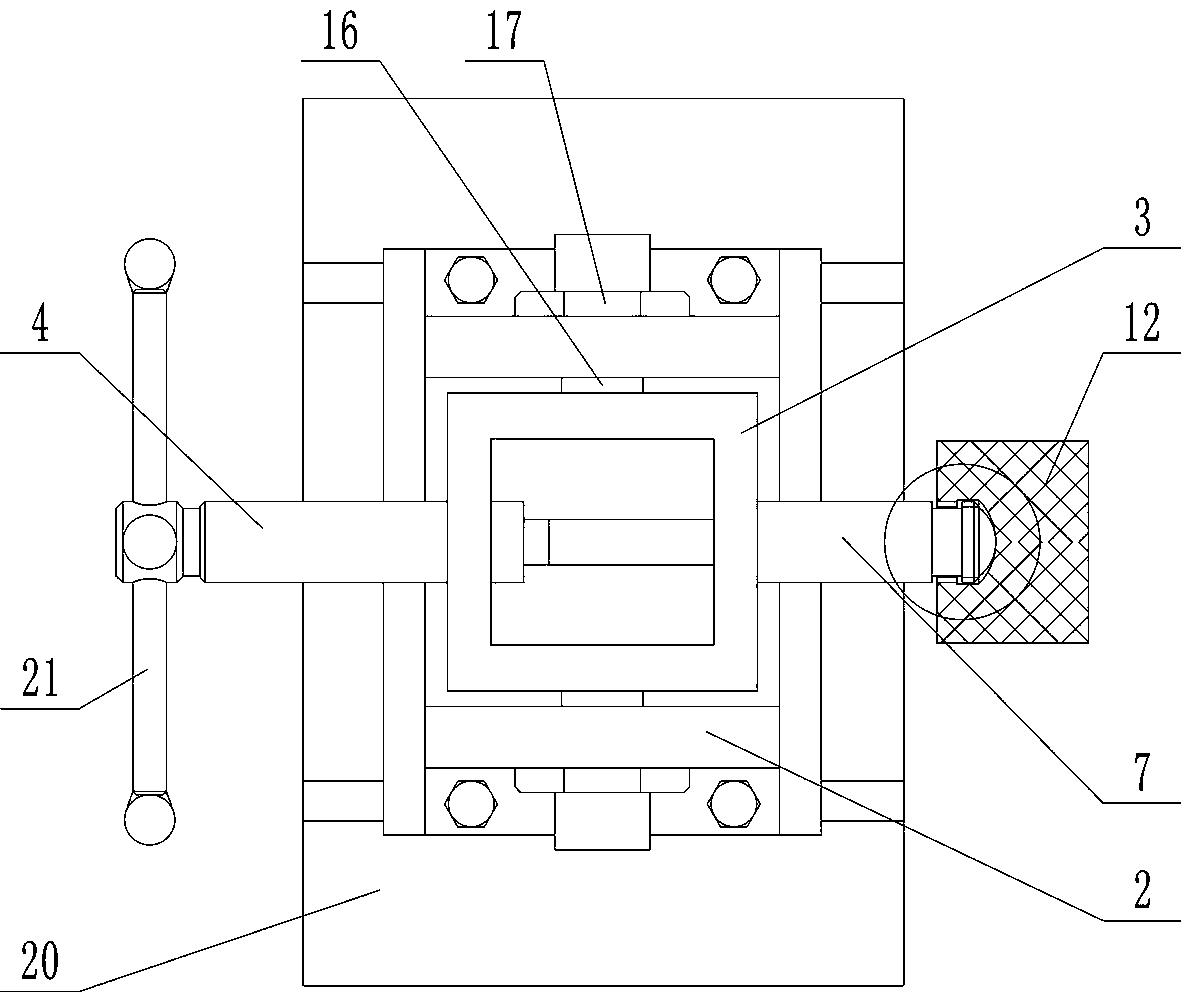
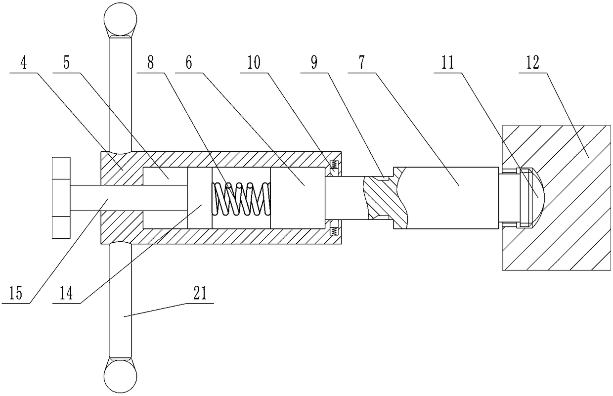
[0016] Depend on Figure 1-6 It can be seen that the present invention includes a horizontally placed base plate 1, two vertical guide plates 2 placed in parallel front and back are provided above the base plate 1, and a slider 3 that can move up and down along the guide plate 2 is provided between the two guide plates 2. The cross section of the slider 3 is in the shape of "back". The left side wall of the slider 3 is interspersed with a screw 4. The screw 4 and the slider 3 are threaded. The right end of the screw 4 is provided with a blind hole 5, and the blind hole 5 A disc 6 that can slide left and right in the blind hole 5 is installed inside, and the disc 6 cannot be separated from the blind hole 5. The right side wall of the slider 3 is interspersed with a push rod 7 that can slide left and right along the slider...


PUM


Abstract

The invention discloses a clamp with controllable clamping force and for machining. Positioning and clamping for a workpiece are achieved very well, the tight-pressing force on the workpiece can be controlled very well, the damages to the workpiece is avoided, and the effect of improving the machining efficiency is achieved on the large-batch production. According to the technical scheme, the clamp comprises a foundation plate; guiding plates are disposed above the foundation plate; a sliding block is disposed between the two guiding plates; a threaded rod is inserted into the left side wall of the sliding block in a penetrating mode; a circular disc is mounted on the threaded rod; an ejector rod is inserted into the sliding block in a penetrating mode; and a spring is connected between the left end of the circular disc and the bottom wall of a blind hole. In an initial state, the circular disc is located on the leftmost side of the blind hole under the action of the spring, wedge grooves which are formed in the right side of the threaded rod and uniformly distributed circumferentially are formed in the outer edge of the ejector rod; clamping blocks which are uniformly distributedcircumferentially and can extend and retract in a radial direction are disposed on the inner wall of the position, matched with the ejector rod, of the threaded rod; and when the threaded rod moves rightwards relative to the ejector rod, the clamping blocks can be clamped into the wedge grooves so that the threaded rod can rotate only in one direction, and the threaded rod can move only leftwardsif the threaded rod rotates in one direction. The clamp is novel in conception.

Description

technical field [0001] The invention relates to the technical field of fixtures for machining, in particular to a fixture for machining with controllable clamping force. Background technique [0002] Aluminum profiles are gradually widely used in the industry. When processing profiles, due to their use occasions and design requirements, the size of the profiles has a large difference, and the profiles need to be clamped during processing to keep them in place. stabilized and then processed. [0003] Among the existing equipment, it is more commonly used to set vises on the workbench, or use cylinder clamps to clamp, and then process the workpiece. When using vises, it takes more time to clamp, but using cylinders When fixing, continuous air supply is required to maintain the stability of the cylinder, which will cause waste of resources, and the use of the cylinder in the workshop will cause a lot of noise, so it is necessary to design a fixture that can quickly and stably ...

Claims


Application Information

Patent Timeline
Patent Type & Authority Applications(China)
IPC IPC(8): B23Q3/06
CPCB23Q3/06
Inventor 田长江白冉马博黄卫刘维桢
Owner 江苏天氟隆防腐设备有限公司
Why Eureka
Try Eureka