High-speed disc type permanent magnet speed regulating device

A permanent magnet speed regulation, disc technology, applied in the direction of electromechanical devices, permanent magnet clutches/brakes, casings/covers/supports, etc., can solve the problem of increasing equipment wear and temperature, reducing equipment service life, axial The movement requirements are very strict, so as to ensure the normal operation, improve the service life, and achieve the effect of good balance

Pending Publication Date: 2019-02-15
江苏科岭能源科技有限公司
View PDF0 Cites 3 Cited by
  • Summary
  • Abstract
  • Description
  • Claims
  • Application Information

AI Technical Summary

Problems solved by technology

[0003] The motor, load and the main body of the permanent magnet eddy current flexible transmission governor are all metal components. The permanent magnet material on the permanent magnet rotor of the permanent magnet eddy current flexible transmission governor and the eddy current magnetic force generated during work have axial attraction, resulting in The rotor of the motor and the load moves axially, and the magnetic force direction of the disk structure is axial, so the requirements for axial movement are very strict. Excessive movement will increase the wear and temperature of the equipment and shorten the service life of the equipment , so we designed a high-speed disc permanent magnet speed control device to solve the above problems

Method used


Image

  • High-speed disc type permanent magnet speed regulating device
  • High-speed disc type permanent magnet speed regulating device
  • High-speed disc type permanent magnet speed regulating device

Examples


Embodiment Construction

[0022] The following will clearly and completely describe the technical solutions in the embodiments of the present invention with reference to the accompanying drawings in the embodiments of the present invention. Obviously, the described embodiments are only some, not all, embodiments of the present invention.

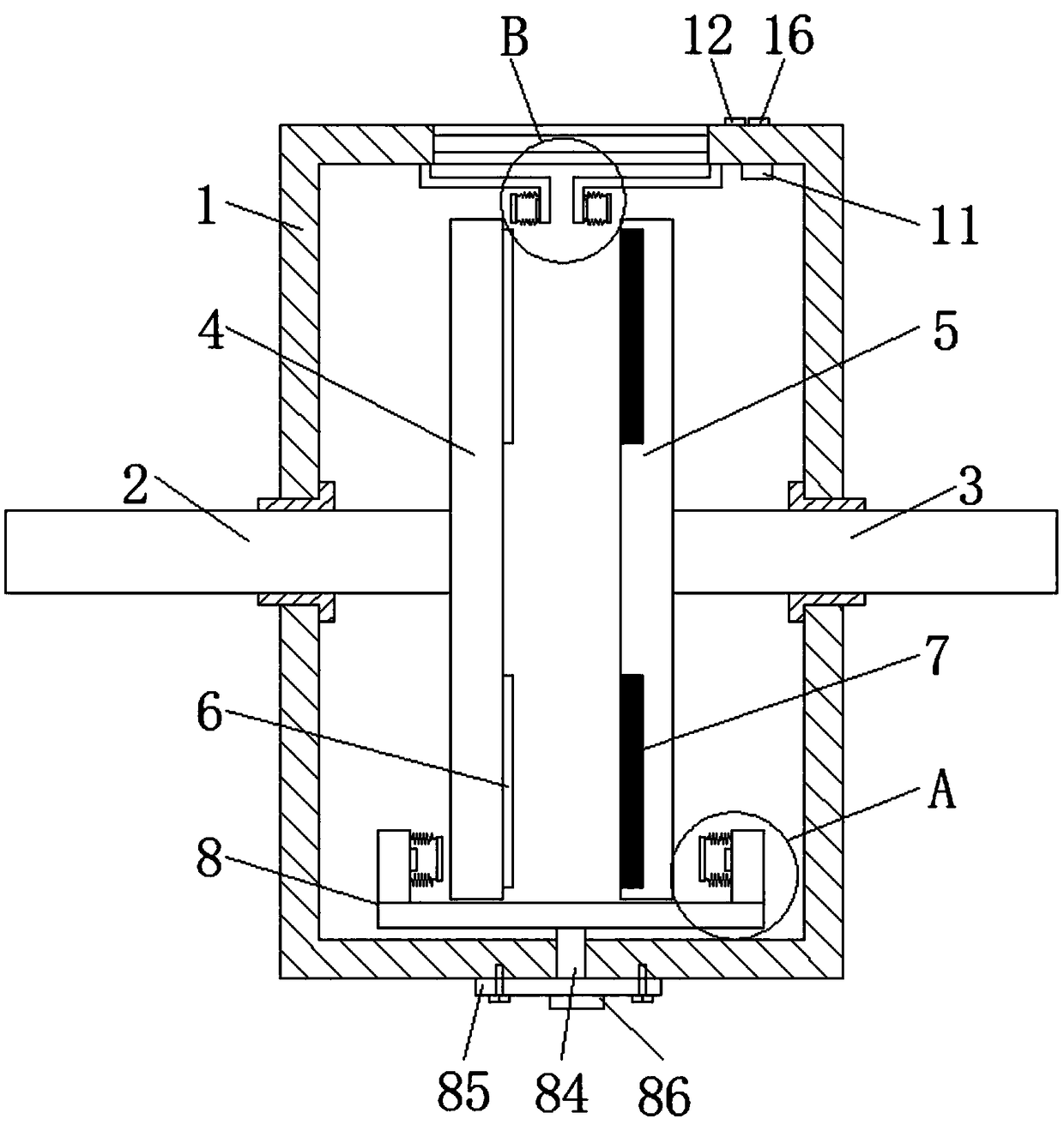
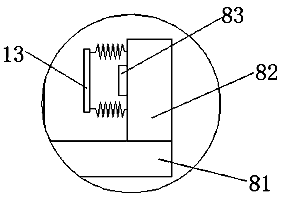
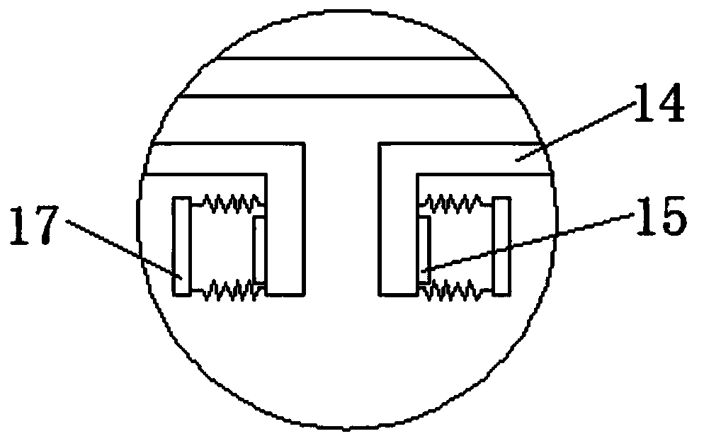
[0023] refer to Figure 1-4 , a high-speed disc-type permanent magnet speed control device, including a housing 1, one end of the housing 1 is connected to an input shaft 2 through a bearing, an output shaft 3 is provided at the end of the housing 1 away from the input shaft 2, and the input shaft 2 and The axes of the output shaft 3 are collinear, and the input shaft 2 and the output shaft 3 are respectively equipped with a conductor disk 4 and a magnet disk 5. The conductor disk 4 is provided with a conductor ring 6 near the end of the magnet disk 5, and the magnet disk 5 is close to the conductor disk 4. One side is embedded with a permanent magnet block 7, and th...


PUM


Abstract

The invention discloses a high-speed disc type permanent magnet speed regulating device, which comprises a casing, wherein one end of the casing is connected with an input shaft through a bearing; anoutput shaft is arranged at one end, far away from the input shaft, of the casing; a conductor disc is arranged on the input shaft; a magnet disc is arranged on the output shaft; a conductor ring is arranged at one end, near the magnet disc, of the conductor disc; a permanent magnet block is embedded in one side, near the conductor disc, of the magnet disc; a lower position limiting warning devicearranged on the casing is arranged at the lower side of the conductor disc and the magnet disc; a window is arranged at one side, far away from the lower position limiting warning device, of the casing; and a temperature sensor is arranged on the inner wall of one side, near the window, of the casing. When the input shaft and the output shaft exceed the allowed jumping range, warning can be givenout; workers can conveniently perform overhaul according to the warning position; meanwhile, warning can be given out when the temperature in the casing is too high; cold air can be timely blown andsupplied by the workers; the service life of parts can be prolonged; and the normal work of the permanent magnet speed regulating device is ensured.

Description

technical field [0001] The invention relates to the field of permanent magnet speed regulating devices, in particular to a high-speed disk type permanent magnet speed regulating device. Background technique [0002] Permanent magnet speed regulation (permanent magnet transmission) is a revolution in the history of transmission. Its simple structure, reliable operation, energy saving and consumption reduction are very well used in modern industries. It is mainly used in petroleum, petrochemical, electric power, mining, The joint regulator of the motor drive system in the steel, chemical, cement and other industries can adjust the relative position of the cylindrical permanent magnet rotor and the cylindrical conductor rotor in the axial direction to change the effective part of the coupling between the permanent magnet rotor and the conductor rotor. The torque transmitted between the two can realize repeatable, adjustable and controllable output torque and speed, and realize ...

Claims


Application Information

Patent Timeline
Patent Type & Authority Applications(China)
IPC IPC(8): H02K49/10H02K5/20
CPCH02K49/106H02K5/20
Inventor 唐煊宇郭祥林王芳
Owner 江苏科岭能源科技有限公司
Why Eureka
Try Eureka