
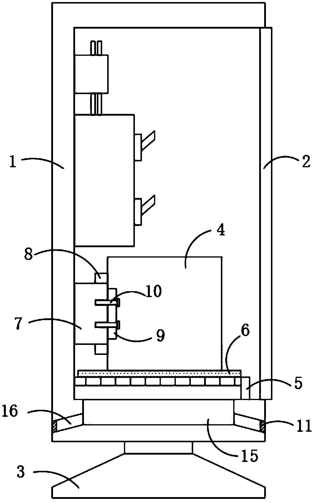
Power distribution box with electric energy control device

A control device and distribution box technology, applied in the cooling/ventilation of substation/switchgear, substation/distribution device shell, substation/switch layout details, etc., can solve the problem of affecting the heat dissipation effect and normal use of distribution boxes Problems such as heat dissipation hole blockage, to achieve the effect of improving stability

Pending Publication Date: 2019-02-15
上科电气集团有限公司
View PDF1 Cites 1 Cited by
  • Summary
  • Abstract
  • Description
  • Claims
  • Application Information

AI Technical Summary

Problems solved by technology

[0004] In the comparison document, the power controller is fixedly installed in the box to realize the power control of the distribution box, and there are cooling holes on the inner bottom of the box. The cooling holes are helpful for the heat dissipation of the box, but only the cooling holes are opened. Its heat dissipation effect is limited, and when the service life is too long, the heat dissipation holes are easily blocked by dust, which seriously affects the heat dissipation effect. Normal use of various components in the electric box

Method used


Image

  • Power distribution box with electric energy control device
  • Power distribution box with electric energy control device
  • Power distribution box with electric energy control device

Examples


Embodiment Construction

[0021] The following will clearly and completely describe the technical solutions in the embodiments of the present invention with reference to the accompanying drawings in the embodiments of the present invention. Obviously, the described embodiments are only some, not all, embodiments of the present invention.

[0022] In describing the present invention, it should be understood that the terms "upper", "lower", "front", "rear", "left", "right", "top", "bottom", "inner", " The orientation or positional relationship indicated by "outside", etc. is based on the orientation or positional relationship shown in the drawings, and is only for the convenience of describing the present invention and simplifying the description, rather than indicating or implying that the referred device or element must have a specific orientation, so as to Specific orientation configurations and operations, therefore, are not to be construed as limitations on the invention.

[0023] refer to Figure ...


PUM


Abstract

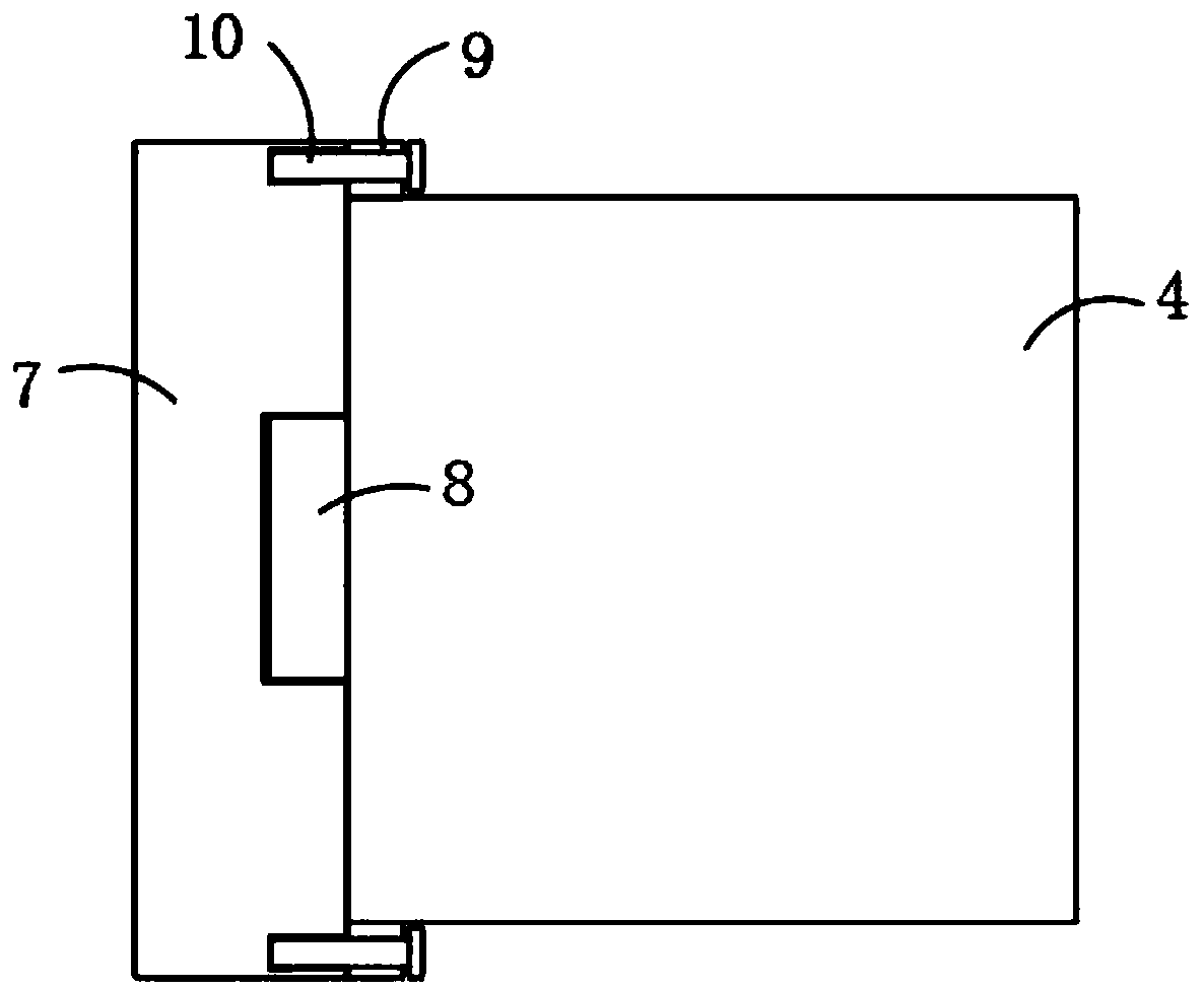
The invention discloses a power distribution box with an electric energy control device. The power distribution box comprises a box body and a box door which is rotationally connected to a side wall of the box body through a hinge; a damp-proof base is fixedly connected to the lower end of the box body; an electric energy control device body is fixedly installed in the box body; a hollow bearing plate for supporting the electric energy control device body is fixedly connected to the inner bottom of the box body; the inner wall of the box body is fixedly connected with a clamping plate; a clamping groove is formed in one side of the clamping plate; a connecting mechanism corresponding to the clamping plate in position is fixedly connected to an opposite side wall of the electric energy control device body; the electric energy control device body is fixedly connected with the clamping groove through a connecting mechanism; and a ventilation mechanism is arranged at the inner bottom of the box body. The power distribution box is simple in structure and convenient to operate; the electric energy control device body is convenient to fix and install; and the ventilation mechanism is arranged at the inner bottom of the box body, so that the heat dissipation and cooling effects in the box body are facilitated.

Description

technical field [0001] The invention relates to the technical field of power distribution and utilization in a distribution box, in particular to a distribution box with an electric energy control device. Background technique [0002] With the rapid development of the economy and society, household appliances and other high-power electrical devices are widely used in various fields and places such as homes, offices, and enterprises, which has greatly increased the electricity consumption of the whole society. Electricity consumption increases greatly, and because people's carelessness and weak awareness of saving cause great energy waste, so an electric energy control device is urgently needed to suppress the waste of electric energy. [0003] After searching, the Chinese patent authorization number is CN 203871698U, which discloses an electric energy distribution box. Composed of the main box body, the main box body is integrally cast from the left side panel, the right si...

Claims


Application Information

Patent Timeline
Patent Type & Authority Applications(China)
IPC IPC(8): H02B1/56H02B1/48H02B1/28
CPCH02B1/565H02B1/28H02B1/48
Inventor 王赞锋陈建叶军叶尊平
Owner 上科电气集团有限公司
Learn More