
Micro-drilling visual detection method and device based on inner-cone mirror surface scanning panoramic imaging

An imaging device and visual inspection technology, applied in wide-screen photography, instruments, optics, etc., can solve problems such as high cost, cumbersome, unstable, etc., to overcome high cost, improve detection efficiency and accuracy, and overcome detection results The effect of uncertainty

Active Publication Date: 2019-02-15
HUAZHONG UNIV OF SCI & TECH +1
View PDF6 Cites 2 Cited by
  • Summary
  • Abstract
  • Description
  • Claims
  • Application Information

AI Technical Summary

Problems solved by technology

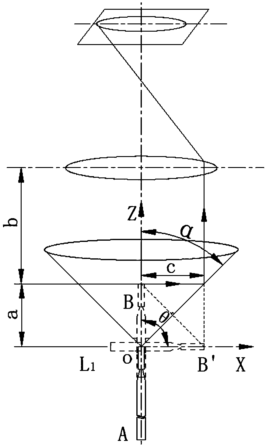
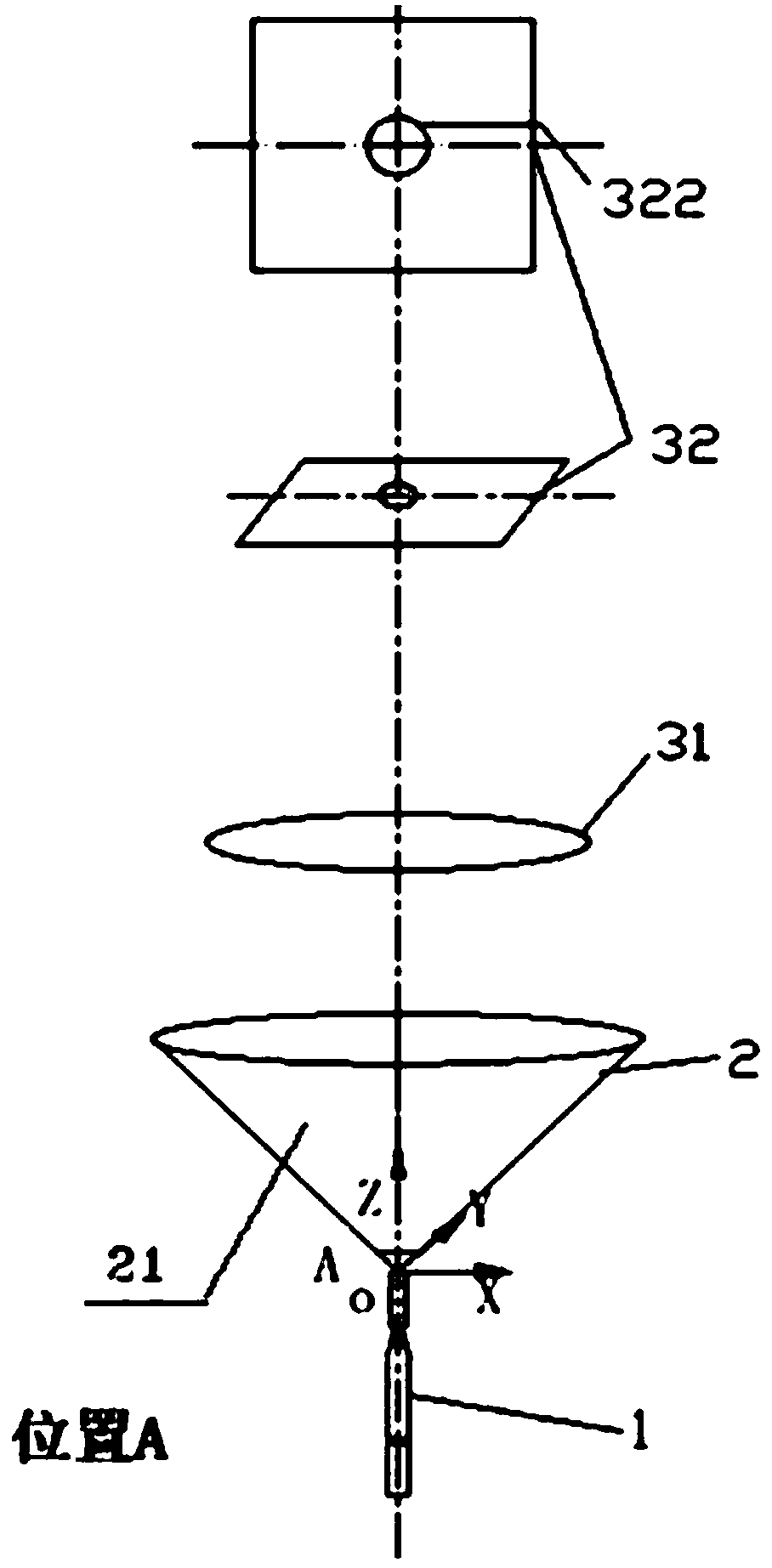
[0005] In view of the above defects or improvement needs of the prior art, the present invention provides a micro-drill visual detection method and device based on inner cone mirror scanning panoramic imaging, which precisely controls the movement of the micro-drill to be inspected through the equipment of the digital motion unit, thereby Realize the acquisition of clear end edge images and multiple consecutive side edge images during the movement process of the micro drill through the hollow cone structure imaging device, and extract the pixels of the side edge images to carry out corresponding expansion and clear images Mechanisms such as belt processing and seamless splicing are organically combined, so that clear, complete and comprehensive side edge images can be obtained without changing the camera viewing angle, thereby overcoming the high cost, cumbersome work steps, and disadvantages of the current micro-drilling detection technology. Detect problems such as dead angles and unstable detection quality, greatly improve the detection efficiency and accuracy of micro-drills, and meet the needs of mass production and detection

Method used


Image

  • Micro-drilling visual detection method and device based on inner-cone mirror surface scanning panoramic imaging
  • Micro-drilling visual detection method and device based on inner-cone mirror surface scanning panoramic imaging
  • Micro-drilling visual detection method and device based on inner-cone mirror surface scanning panoramic imaging

Examples


Embodiment Construction

[0055] In order to make the object, technical solution and advantages of the present invention clearer, the present invention will be further described in detail below in conjunction with the accompanying drawings and embodiments. It should be understood that the specific embodiments described here are only used to explain the present invention, not to limit the present invention. In addition, the technical features involved in the various embodiments of the present invention described below can be combined with each other as long as they do not constitute a conflict with each other.

[0056] like figure 1 As shown, the micro-drill visual inspection system based on inner cone mirror scanning panoramic imaging in this embodiment includes an inner cone mirror annular local imaging device 2, an imaging device 3, an image acquisition card 4, a computer 5, a servo drive 6 and a lifting platform 7. Among them, the inner cone mirror annular partial imaging device 2 is connected to t...


PUM

PropertyMeasurementUnit
Cone angleaaaaaaaaaa
Hole diameteraaaaaaaaaa

Abstract

The invention belongs to the technical field of micro-drilling visual quality detection, and discloses a micro-drilling visual detection method based on inner-cone mirror surface scanning panoramic imaging. The method simultaneously adopts a device with an inner cone mirror surface annular local imaging device, an image acquisition and processing unit and a digital motion unit; firstly, an image with a clear end edge is shot and obtained, and if the end edge is judged to be qualified, continuous shooting is performed to obtain a plurality of side edge images, the side edge images are unfoldedto extract image clear bands, and then a final clear and complete side edge image is obtained through splicing. The invention further provides a micro-drilling visual detection system using the method. According to the invention, in a one-time motion process, the clear, complete and all-around side edge images can be obtained without converting a shooting view angle of a camera, so that the problems that the current micro-drilling detection technology is high in cost, has the detection dead angle, is unstable in detection quality and the like are overcome, the detection efficiency and precision of the micro-drill are greatly improved, and the requirements of batch production and detection are met.

Description

technical field [0001] The invention belongs to the technical field of visual quality detection of micro-drills, and more specifically relates to a micro-drill visual detection method and device based on inner cone mirror surface scanning panoramic imaging. Background technique [0002] Micro-drills (referred to as micro-drills) are mainly used in dental treatment and printed circuit board processing, and the diameter of micro-drills is generally less than 2mm. With the improvement of living standards, people pay more and more attention to oral health issues, and the quality of micro drills directly affects the effect of dental treatment. The quality inspection technology of dental micro-drills has become a difficult problem in the micro-drill production industry; at the same time, with the increasing integration of printed circuit boards, the diameter of micro-drills for processing small holes in circuit boards continues to decrease, and the difficulty of quality inspection...

Claims


Application Information

Patent Timeline
IPC IPC(8): G03B37/02
CPCG03B37/02
Inventor 王平江曹普信张锴余凌波黄成陈子和张顺林黄龙贤宁雪燕
Owner HUAZHONG UNIV OF SCI & TECH
Learn More