Foundation pit pumping device

A technology for pumping devices and foundation pits, which is applied in pump devices, components of pumping devices for elastic fluids, infrastructure engineering, etc., can solve problems such as pump damage, pumping pipeline damage, and shortening the service life of the pump , to achieve the effect of convenient use, energy saving and speeding up the flow rate

Inactive Publication Date: 2019-02-15
郑州天狼实业有限公司
View PDF0 Cites 3 Cited by
  • Summary
  • Abstract
  • Description
  • Claims
  • Application Information

AI Technical Summary

Problems solved by technology

[0002] When the foundation pit is excavated, the infiltration of groundwater and surface water will cause water accumulation, and rainy days will also cause water accumulation in the foundation pit during construction. To ensure smooth excavation, shallow foundations or foundation pits with little water, generally keep a certain drainage slope at the bottom of the pit during excavation, and dig water collection ditches at low places to divert water, and set up a water collection well every 30~40cm Outside the scope of the foundation pit, the bottom of the water collection well should be about 1 lower than the water collection ditch, and then the pump is put into the water collection well to pump water. However, when the existing water pipe enters the water collection well, due to the deep water depth It is difficult to stretch into the bottom of the collection well for pumping, which greatly reduces the efficiency of pumping, and in the process of pumping, because there are often gravel and stones in the foundation pit, during the pumping process, gravel and stones will not only damage the pump , will also cause damage to the suction pipe, greatly reducing the service life of the suction pump, therefore, the existing technology needs further improvement

Method used


Image

  • Foundation pit pumping device
  • Foundation pit pumping device
  • Foundation pit pumping device

Examples


Embodiment 1

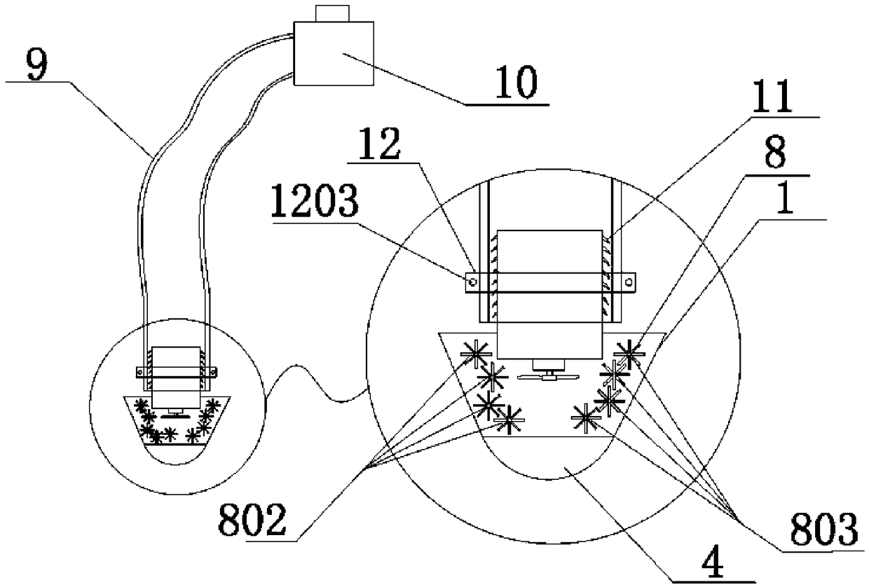
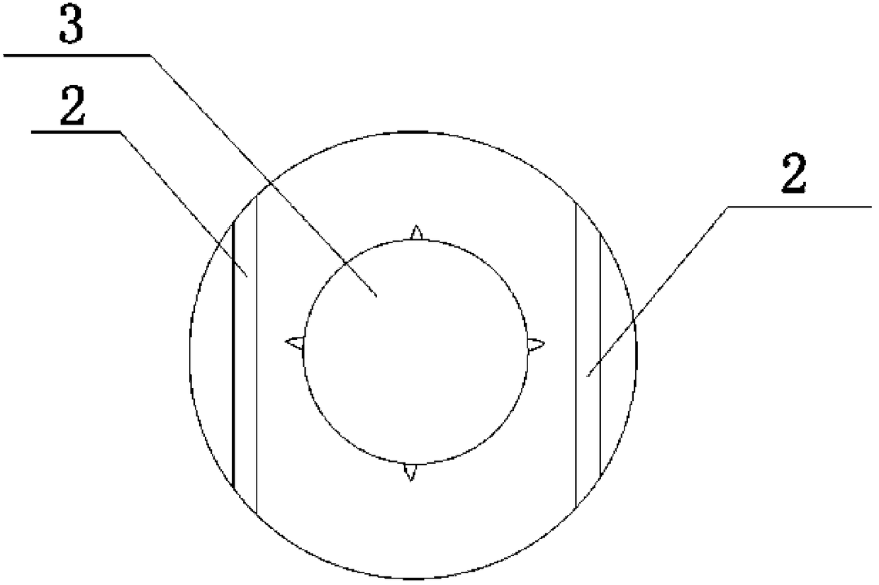
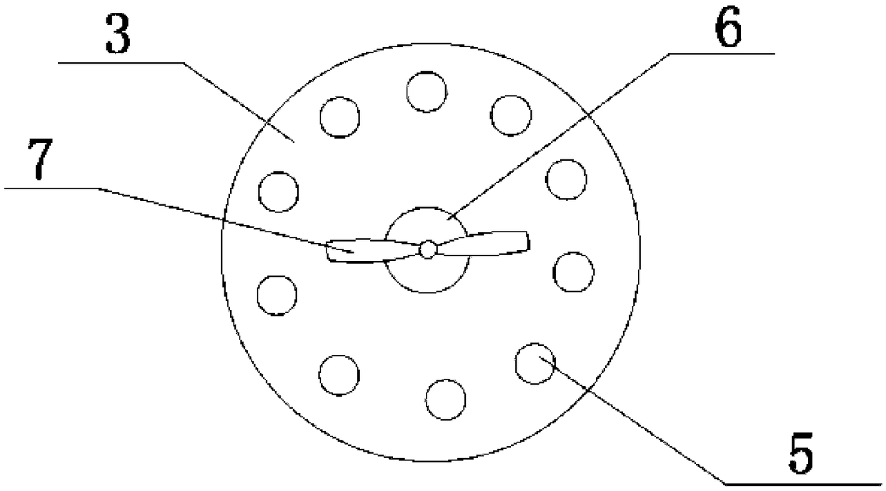
[0020] Such as Figure 1-5 The pumping device for a foundation pit shown includes a sand discharge chamber 1, which is in the shape of a circular platform, and the upper end surface of the sand discharge chamber 1 is larger than the lower end surface, and the upper end surface of the sand discharge chamber 1 is provided with two openings 2, two Two openings 2 are respectively located on both sides of the fixed box 3, the fixed box 3 is a cylindrical cavity structure, the lower end surface of the sand discharge chamber 1 is fixedly connected with the gravity block 4, and the center position of the upper end surface of the sand discharge chamber 1 is also connected with the fixed box 3, The upper end of the fixed box 3 protrudes from the upper surface of the sand discharge chamber 1, and the lower end of the fixed box 3 extends into the sand discharge chamber 1. The fixed box 3 is provided with several water flow channels 5 for water flow, and the water flow channels 5 are from t...

Embodiment 2

[0023] The difference between embodiment 1 and embodiment 2 is that the width of the opening 2 is 3 mm.

Embodiment 3

[0025] The difference between embodiment 1 and embodiment 3 is that the width of the opening 2 is 4mm.


PUM

PropertyMeasurementUnit
Widthaaaaaaaaaa
Widthaaaaaaaaaa

Abstract

The invention belongs to the technical field of construction equipment, and particularly relates to a foundation pit pumping device. The foundation pit pumping device includes a sand discharge cavity,openings, a fixing box, a gravity block, water flow channels, a rotary motor, an impeller, runners, rotating shafts, first groups of runners, second groups of runners, a pumping pipeline, a water pump, barbs, clamps, semi-circular arc-shaped pieces, connecting pieces and through holes, the sand discharge cavity is in a round table shape, the upper end face of the sand discharge cavity is larger than the lower end face of the sand discharge cavity, and the upper end face of the sand discharge cavity is provided with the two openings which are located on both sides of the fixing box correspondingly; and the lower end face of the sand discharge cavity is fixedly connected with the gravity block, the center position of the upper end face of the sand discharge cavity is further connected withthe fixing box, the upper end of the fixing box extends out of the upper end of the sand discharge cavity, and the lower end of the fixing box extends into the sand discharge cavity. According to thefoundation pit pumping device, use is convenient, and the service life is long.

Description

technical field [0001] The invention belongs to the technical field of construction equipment, and in particular relates to a foundation pit pumping device. Background technique [0002] When the foundation pit is excavated, the infiltration of groundwater and surface water will cause water accumulation, and rainy days will also cause water accumulation in the foundation pit during construction. To ensure smooth excavation, shallow foundations or foundation pits with little water, generally keep a certain drainage slope at the bottom of the pit during excavation, and dig water collection ditches at low places to divert water, and set up a water collection well every 30~40cm Outside the scope of the foundation pit, the bottom of the water collection well should be about 1 lower than the water collection ditch, and then the pump is put into the water collection well to pump water. However, when the existing water pipe enters the water collection well, due to the deep water dep...

Claims


Application Information

Patent Timeline
IPC IPC(8): F04D13/08F04D13/12F04D29/70F04D29/60F04D29/40E02D19/10
CPCF04D13/08E02D19/10F04D13/12F04D29/406F04D29/605F04D29/708
Inventor 唐封民
Owner 郑州天狼实业有限公司
Why Eureka
Try Eureka