Placement rack for flexible graphite ground wires

A flexible graphite and grounding wire technology, applied in the field of electrical equipment, can solve the problems of insufficient use effect and adaptability of the grounding wire storage rack, and achieve the effects of simple structure, strong practicability and convenient access.

Inactive Publication Date: 2019-02-15
ANHUI HUAXI ELECTRIC POWER TECH CO LTD
View PDF10 Cites 1 Cited by
  • Summary
  • Abstract
  • Description
  • Claims
  • Application Information

AI Technical Summary

Problems solved by technology

[0005] The use effect and adaptability of the grounding wire storage rack involved in the above comparative documents are not good enough. Therefore, a more reasonable design is required for the rack used in flexible graphite grounding wires

Method used


Image

  • Placement rack for flexible graphite ground wires
  • Placement rack for flexible graphite ground wires
  • Placement rack for flexible graphite ground wires

Examples


Embodiment 1

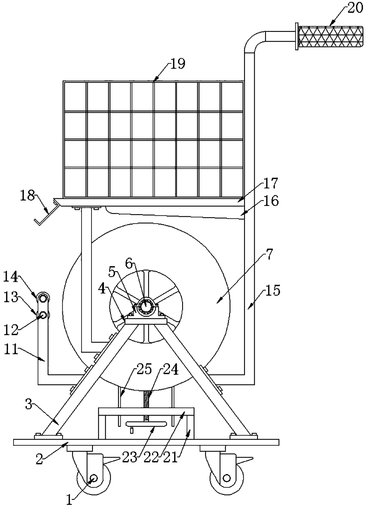
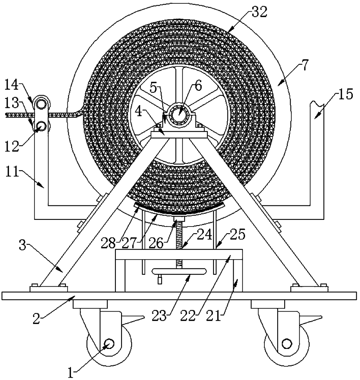
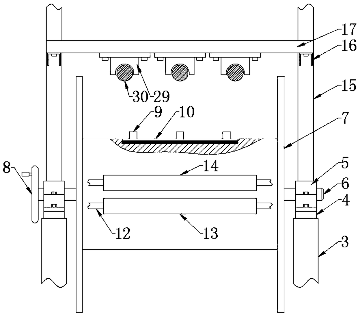
[0021] Such as Figure 1 to Figure 4 As shown, a placement frame for flexible graphite grounding wires includes a bottom plate 2 and a roller support frame 3, and the roller support frame 3 is symmetrically installed on the bottom plate 2 left and right, and the top of the roller support frame 3 is provided with a mounting plate -4, the mounting plate -4 is equipped with a bearing seat 5 through screws, the bearing seat 5 is provided with a roller bearing and a roller support shaft 6 is installed in rotation, and the left end of the roller support shaft 6 is provided with a hand wheel- 8. A roller 7 is fixedly installed on the roller support shaft 6, three pins 9 are arranged on the working surface of the roller 7 and a magnet 10 is arranged directly below it, and a vertical support is arranged directly below the roller 7 Plate 21 and horizontal support plate 22, described horizontal support plate 22 is installed on the upper end surface of base plate 2 by vertical support pla...

Embodiment 2

[0024] Such as Figure 1 to Figure 4 As shown, a placement frame for flexible graphite grounding wires includes a bottom plate 2 and a roller support frame 3, and the roller support frame 3 is symmetrically installed on the bottom plate 2 left and right, and the top of the roller support frame 3 is provided with a mounting plate -4, the mounting plate -4 is equipped with a bearing seat 5 through screws, the bearing seat 5 is provided with a roller bearing and a roller support shaft 6 is installed in rotation, and the left end of the roller support shaft 6 is provided with a hand wheel- 8. A roller 7 is fixedly installed on the roller support shaft 6, three pins 9 are arranged on the working surface of the roller 7 and a magnet 10 is arranged directly below it, and a vertical support is arranged directly below the roller 7 Plate 21 and horizontal support plate 22, described horizontal support plate 22 is installed on the upper end surface of base plate 2 by vertical support pla...


PUM


Abstract

The invention discloses a placement rack for flexible graphite ground wires, and relates to the technical field of electrical equipment. The placement rack comprises a bottom plate and roller supporting frames; the roller supporting frames are mounted on the bottom plate in a bilateral symmetry mode, and first mounting plates are arranged at the tops of the roller supporting frames; bearing seatsare mounted on the first mounting plates through screws, and the bearing seats are internally provided with roller bearings and rotationally provided with roller supporting shafts; first hand wheels are arranged at the left ends of the roller supporting shafts, and rollers are fixedly mounted on the roller supporting shafts; three pins are arranged on the working faces of the rollers, and magnetsare arranged under the pins; vertical supporting plates and horizontal supporting plates are arranged under the rollers, and the horizontal supporting plates are mounted on the upper end face of the bottom plate through the vertical supporting plates; and threaded rods are mounted on the horizontal supporting plates in a threaded mode, and the tops of the threaded rods are provided with connectingblocks and connected with arc-shaped stop plates through the connecting blocks. Wiring noses on the graphite ground wires are clamped into the pins on the rollers, and then the ground wires can be stored by shaking the first hand wheels.

Description

technical field [0001] The invention relates to the technical field of electrical equipment, in particular to a placement frame for flexible graphite grounding wires. Background technique [0002] The grounding line is the line directly connected to the earth, and it can also be called a safety return line. When it is in danger, it will directly transfer the high voltage to the earth, which can be regarded as a lifeline. In the power system, the grounding wire is an important tool to ensure the staff in the event of unexpected voltage on the equipment and lines that have been powered off. When electric workers maintain and repair power supply circuits, they must install and use grounding wires to achieve the purpose of protecting personal and equipment safety. However, grounding wires are generally reused. After the first use, the wires and The ground electrode is wound on the hanging rod of the ground wire, which is inconvenient to carry and use next time. [0003] The Ch...

Claims


Application Information

Patent Timeline
IPC IPC(8): B65H75/40
Inventor 张腾翟慧阳郭红张文冰
Owner ANHUI HUAXI ELECTRIC POWER TECH CO LTD
Why Eureka
Try Eureka