
Optical fiber disc production line

A technology for production lines and optical fiber trays, applied in conveyors, mechanical conveyors, conveyor objects, etc., can solve the problems of difficult to guarantee product quality, high product defect rate, and large labor consumption, so as to facilitate subsequent operations, reduce The defect rate and the effect of improving production efficiency

Pending Publication Date: 2019-02-15
KUNSHAN SPARK MATERIALS CO LTD
View PDF0 Cites 1 Cited by
  • Summary
  • Abstract
  • Description
  • Claims
  • Application Information

AI Technical Summary

Problems solved by technology

[0003] In the production process of optical fiber discs, procedures such as injection molding, assembly, welding and testing are required. After the optical fiber discs are injected from the injection molding machine, the subsequent assembly, welding and testing procedures are generally carried out manually for optical fiber discs. Subsequent processing realizes the assembly, welding and testing of optical fiber disks. However, the manual method consumes a lot of manpower, is inefficient, and requires high costs. Moreover, the final product formed by manual operation has a high defective rate, and the quality of the product is difficult to obtain. Guarantee, it is difficult to meet the needs of modern high-speed production

Method used


Image

  • Optical fiber disc production line
  • Optical fiber disc production line
  • Optical fiber disc production line

Examples


Embodiment Construction

[0032] The present invention will now be further described in detail in conjunction with the accompanying drawings and embodiments. These drawings are all simplified schematic diagrams, only illustrating the basic structure of the present invention in a schematic manner, so it only shows the composition related to the present invention.

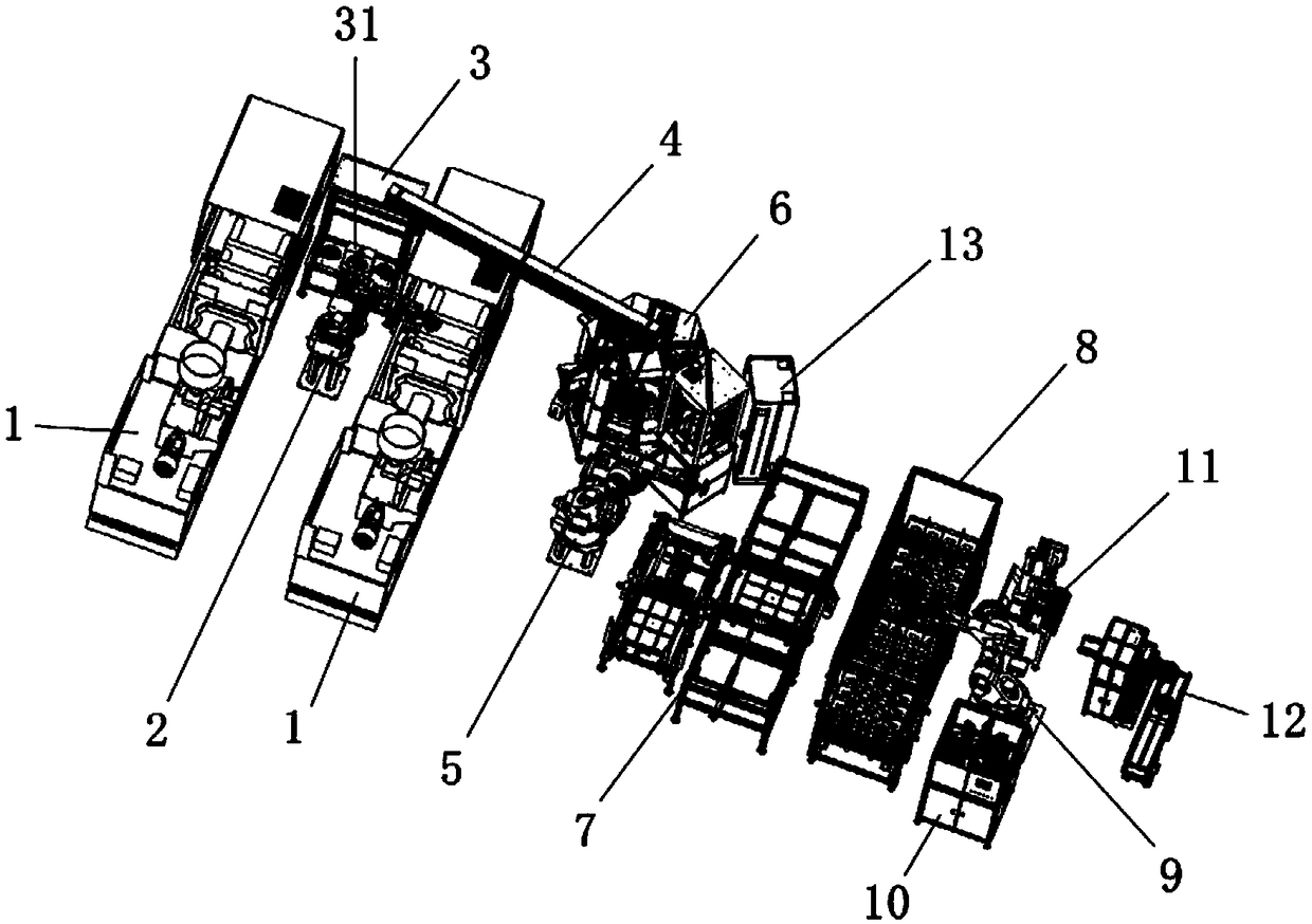
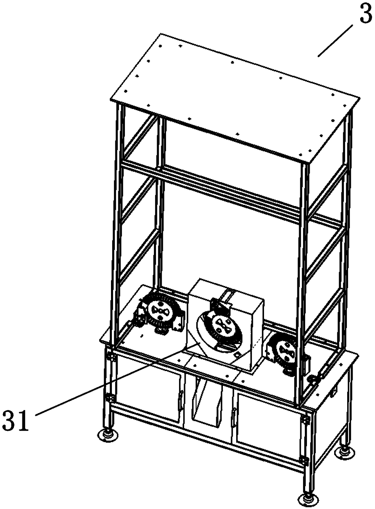
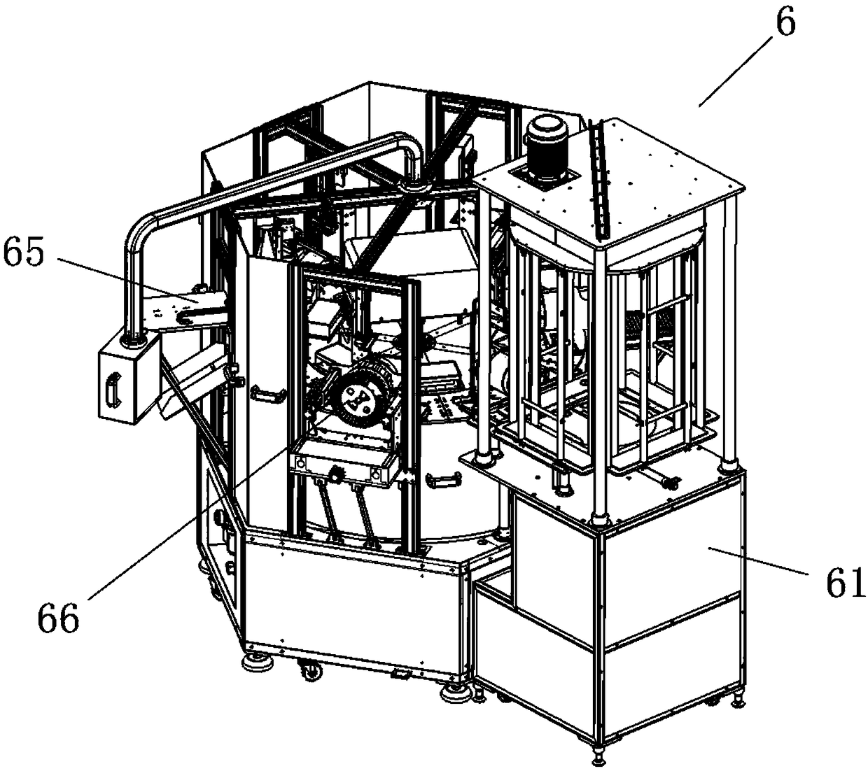
[0033] Such as Figure 1 to Figure 9As shown, an optical fiber disk production line includes: an injection molding station, the injection molding station includes a plurality of injection molding machines 1, a first manipulator 2 is arranged on one side of the injection molding machine 1, and the injection molding machine 1 is located within the operating range of the first manipulator 2; The burr removal station 3 is located within the operating range of the first manipulator 2. The burr removal station 3 includes a burr removal mechanism 31; the burr removal mechanism 31 includes a burr removal motor and a burr removal scraper, and the burr ...


PUM


Abstract

The invention discloses an optical fiber disc production line. The optical fiber disc production line comprises a collodion processing station, an ejection ring storage and taking station, a welding station, a detection station and an electric control box. The collodion processing station comprises a collodion feeding mechanism, a collodion circling mechanism, a collodion welding mechanism, a collodion cooling mechanism, a collodion detection mechanism and a collodion assembly mechanism. The ejection ring storage and taking station comprises an ejection ring storage and taking drive mechanism,ejection ring storage mechanisms, an ejection ring lifting mechanism and an ejection ring feeding induction mechanism. The welding station comprises an ultrasonic welder, a welding sliding mechanismand a welding locating mechanism. The detection station comprises a detection feeding mechanism, a detection locating mechanism, a detection mechanism and a detection discharging mechanism. A PLC is arranged in the electric control box. According to the optical fiber disc production line, manual operation is avoided, subsequent operation can be continuously and stably carried out on optical fiberdiscs, the quality of finished products is guaranteed, and the defective rate is reduced; and the production efficiency is greatly improved, manpower consumption is reduced, and cost is reduced.

Description

technical field [0001] The invention belongs to the technical field of optical fiber disk production, and in particular relates to an optical fiber disk production line. Background technique [0002] Optical fiber reels are mainly used in the field of optical communications, and in the testing of optical cable construction and maintenance. [0003] In the production process of optical fiber discs, procedures such as injection molding, assembly, welding and testing are required. After the optical fiber discs are injected from the injection molding machine, the subsequent assembly, welding and testing procedures are generally carried out manually for optical fiber discs. Subsequent processing realizes the assembly, welding and testing of optical fiber disks. However, the manual method consumes a lot of manpower, is inefficient, and requires high costs. Moreover, the final product formed by manual operation has a high defective rate, and the quality of the product is difficult ...

Claims


Application Information

Patent Timeline
Patent Type & Authority Applications(China)
IPC IPC(8): B65G47/90B65G47/74B65G37/00
CPCB65G37/00B65G47/74B65G47/90
Inventor 任华平
Owner KUNSHAN SPARK MATERIALS CO LTD
Learn More