Domestic intelligent trash can
A trash can, intelligent technology, applied in the field of daily necessities, can solve the problems of single function, inconvenience, limited adsorption capacity of activated carbon, etc., and achieve the effect of prolonging the service life
- Summary
- Abstract
- Description
- Claims
- Application Information
AI Technical Summary
Problems solved by technology
Method used
Image

Examples
Embodiment 1
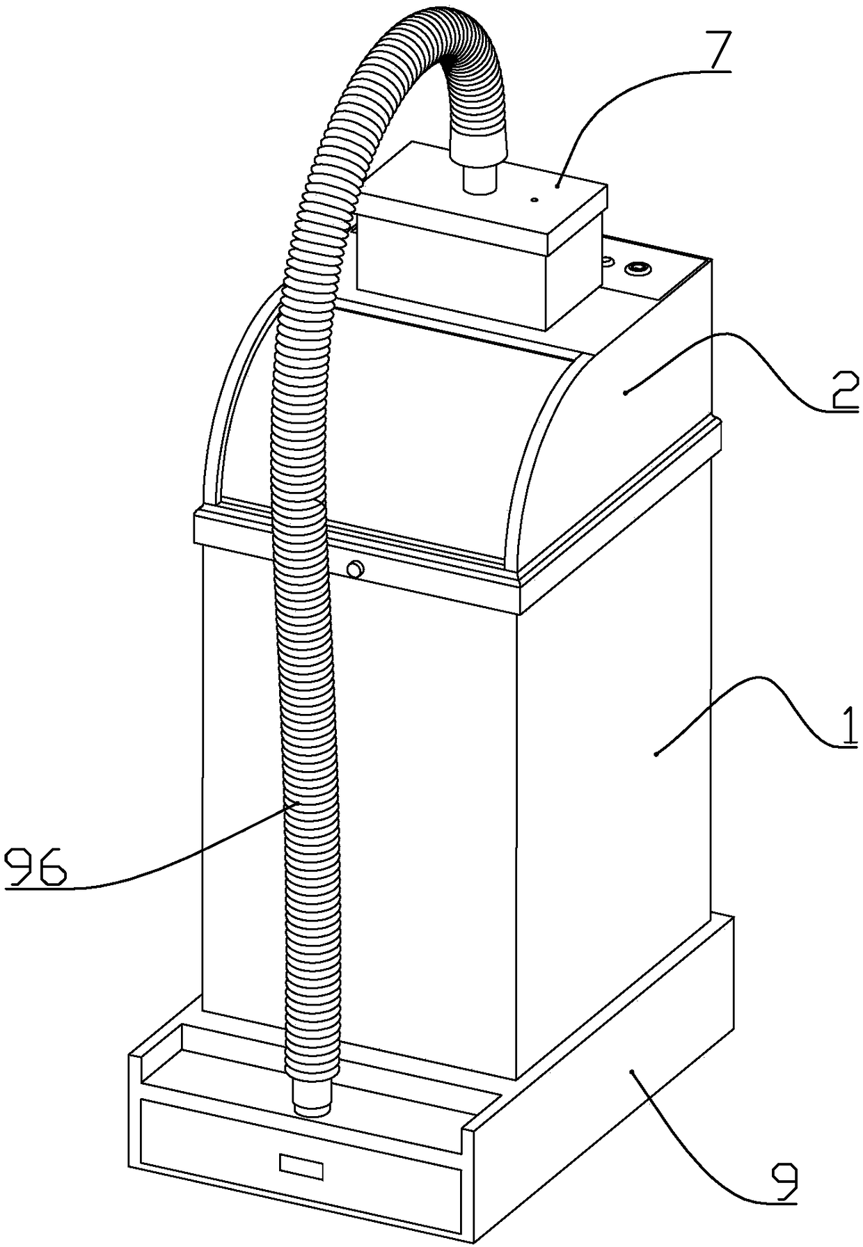
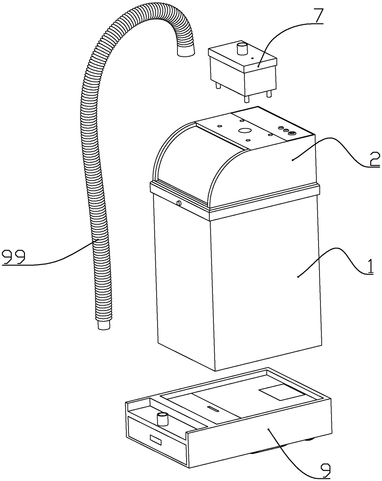
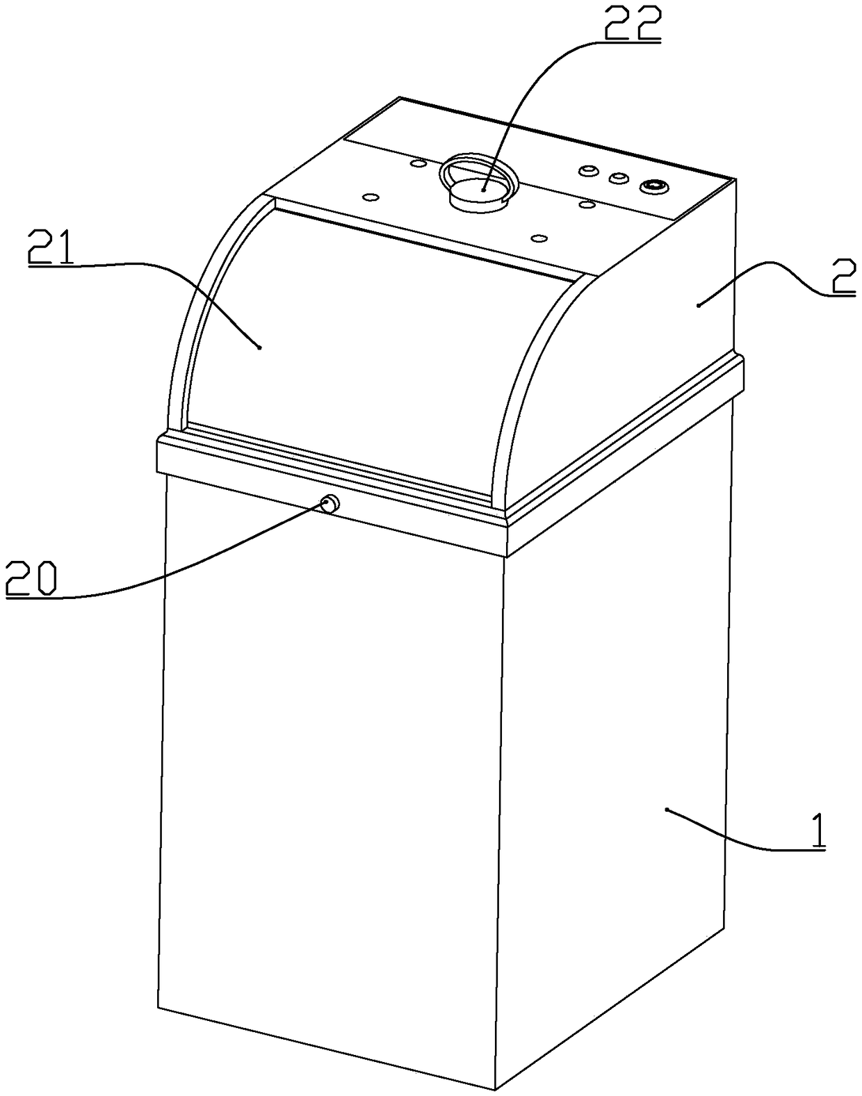
[0059] according to Figure 1 to Figure 18 As shown, the present embodiment is a kind of household intelligent trash can, which includes a cuboid-shaped outer barrel 1 with an open upper end, a cylindrical inner barrel 3 installed in the outer barrel from top to bottom, and a detachable sleeve on the upper end of the outer barrel. The barrel lid 2.
[0060] The front upper part of the lid is formed with an arc-shaped garbage throwing inlet, and the two sides of the garbage throwing inlet are symmetrically formed with baffle guide grooves 207 on the bung, and the two baffle guide grooves on both sides are slidably installed. There is an elastic baffle 21 in order to block the entrance of the garbage dump; two baffle mounting brackets 206 are formed at the corresponding baffle guide groove at the lower end of the front side of the bung, and the lower end of the baffle guide groove faces toward the Extending down to the bottom of the baffle mounting frame, the garbage throwing i...
Embodiment 2
[0087] In this embodiment, the following improvements are made on the basis of Embodiment 1: a magnet a is installed at the bottom of the outer tub, and a magnet b is attached to the bottom of the outer tub and fixed with the magnet a by magnetic force. This facilitates disassembly and assembly between the outer barrel and the mopping assembly.
[0088] A drive motor for respectively driving the two drive wheels is installed in the base, a control box 93 is installed at a position between the two drive wheels in the base, and a battery and a circuit board are installed in the control box. The driving motor and the battery of the driving wheel are respectively electrically connected to the circuit board.
[0089] The lower end of the roller clamping groove is open, and the position near the lower end of the roller clamping groove is formed with a limit protrusion to prevent the rotating head of the roller from being separated from the roller clamping groove automatically. Coop...
Embodiment 3
[0092] combine Figure 5 , Figure 19 and Figure 20 In this embodiment, the following improvements are made on the basis of Embodiment 1 or 2: a support bead 34 is formed on the upper periphery of the inner barrel, and a rotating ring 8 is provided on the outer periphery of the inner barrel above the support bezel. The outer wall of the rotating ring 8 is formed with 5-8 groups of wheel seats 801, and each group of wheel seats is rotatably connected with a thermoplastic material or a soft silicone material viscous wheel 802, between the viscous wheel and the pin shaft is The interference fit rotation connection makes the viscous wheel need to overcome the frictional force when rotating relative to the pin shaft; the outer wall of the rotation ring is located below the wheel seat and equidistantly installed with driven magnets 803, and the inner barrel baffle of the bucket lid is located below the rotation ring A sealing motor 81 that drives the rotating ring to rotate is in...
PUM
 Abstract
Description
Claims
Application Information
 - R&D
- Intellectual Property
- Life Sciences
- Materials
- Tech Scout
- Unparalleled Data Quality
- Higher Quality Content
- 60% Fewer Hallucinations
Browse by: Latest US Patents, China's latest patents, Technical Efficacy Thesaurus, Application Domain, Technology Topic, Popular Technical Reports.
© 2025 PatSnap. All rights reserved.Legal|Privacy policy|Modern Slavery Act Transparency Statement|Sitemap|About US| Contact US: help@patsnap.com