
Lower connection structure of landing gear buffer

A landing gear buffer and connecting structure technology, which is applied in the direction of landing gear, aircraft parts, transportation and packaging, etc., can solve the problems that cannot meet the requirements of high load transmission, and achieve the effect of improving fatigue strength

Active Publication Date: 2019-02-15
SHENYANG AIRCRAFT DESIGN INST AVIATION IND CORP OF CHINA
View PDF5 Cites 0 Cited by
  • Summary
  • Abstract
  • Description
  • Claims
  • Application Information

AI Technical Summary

Problems solved by technology

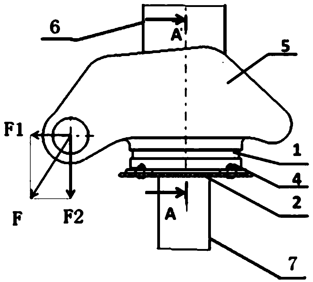
[0003] At present, the load-bearing nut of the lower connection structure of the front landing gear buffer of a catapult take-off carrier-based aircraft bears an ejection load of more than ten tons during the catapult take-off. In the traditional lower connection structure, the load-bearing nut and the landing gear buffer adopt ordinary or MJ tooth type. The threaded connection cannot meet the requirements of transmitting high loads

Method used


Image

  • Lower connection structure of landing gear buffer
  • Lower connection structure of landing gear buffer
  • Lower connection structure of landing gear buffer

Examples


Embodiment Construction

[0046] In order to make the purpose, technical solution and advantages of the application more clear, the technical solution in the embodiment of the application will be described in more detail below in conjunction with the drawings in the embodiment of the application. In the drawings, the same or similar reference numerals denote the same or similar elements or elements having the same or similar functions throughout. The described embodiments are some, but not all, embodiments of the application. The embodiments described below by referring to the figures are exemplary, and are intended to explain the present application, and should not be construed as limiting the present application. Based on the embodiments in this application, all other embodiments obtained by persons of ordinary skill in the art without creative efforts fall within the protection scope of this application. Embodiments of the present application will be described in detail below in conjunction with th...


PUM


Abstract

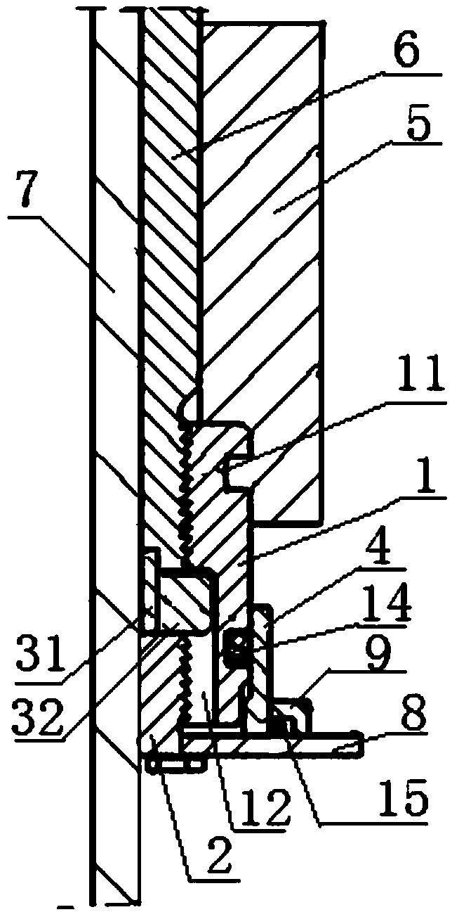
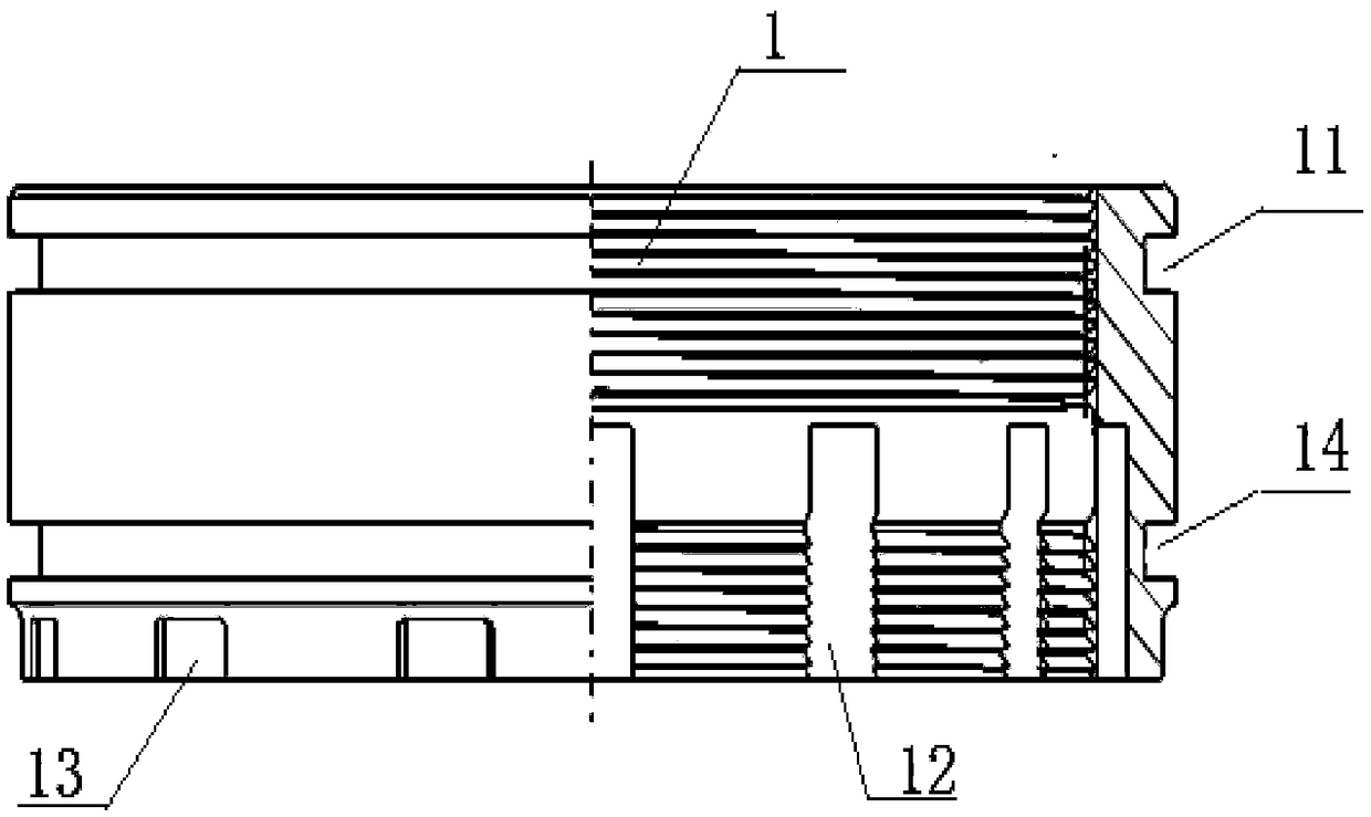
The invention belongs to the technical field of landing gear structure designs, and particularly relates to a lower connection structure of a landing gear buffer. The buffer comprises: an outer barreland a piston rod; one end of the piston rod is disposed inside the outer barrel; and the lower connection structure comprises a rotating sleeve and a bearing nut; the rotating sleeve is arranged at the periphery of the outer barrel in a sleeving manner; an ejection connection structure is arranged outside the rotating sleeve; the ejection connection structure is connected with an ejection rod; one end of the bearing nut is arranged between the outer barrel and the rotating sleeve and is called as a bearing nut upper end; the other end of the bearing nut is called a bearing nut lower end; theinner wall of the bearing nut upper end and the outer wall of the outer barrel are fitted and connected through sawtooth-shaped threads; the outer wall of the bearing nut upper end and the inner wallof the rotating sleeve are fitted and connected through a bearing slot formed along a circumferential direction and a bearing protrusion disposed along the circumferential direction; the rotating sleeve can rotate relative to the bearing nut.

Description

technical field [0001] The application belongs to the technical field of landing gear structure design, and in particular relates to a lower connection structure of a landing gear buffer. Background technique [0002] Aircraft landing gear is designed to ensure the safety of the two stages of takeoff and landing, and its core component is the buffer, which is used to consume the sliding load of the aircraft during the two stages of takeoff and landing. The lower connection structure is designed on the landing gear buffer to transfer the loads such as wheels and tires to the landing gear and aircraft structure. [0003] At present, the load-bearing nut of the lower connection structure of the front landing gear buffer of a catapult take-off carrier-based aircraft bears an ejection load of more than ten tons during the catapult take-off. In the traditional lower connection structure, the load-bearing nut and the landing gear buffer adopt ordinary or MJ tooth type. The threade...

Claims


Application Information

Patent Timeline
Patent Type & Authority Applications(China)
IPC IPC(8): B64C25/32
CPCB64C25/32
Inventor 宋得军徐燕苑强波倪艳红李福
Owner SHENYANG AIRCRAFT DESIGN INST AVIATION IND CORP OF CHINA
Learn More