aircraft support frame

A technology for supporting skeletons and skeletons, applied to aircraft parts, fuselages, transportation and packaging, etc., can solve problems such as difficult assembly, long production cycle, and interruption of parts, and achieve the goals of reducing weight burden, direct load transmission, and reducing quantity Effect

Active Publication Date: 2021-02-26
CHINA HELICOPTER RES & DEV INST
View PDF5 Cites 0 Cited by
  • Summary
  • Abstract
  • Description
  • Claims
  • Application Information

AI Technical Summary

Problems solved by technology

The parts that are combined and assembled to form a supporting skeleton are mostly made of molds. In the production process, a large number of molds are used. There are many assembly surfaces and tooling positions, and the production cycle is long. In most cases, there are a large number of molds. The curved surface and the separation surface of the process are not easy to set, which makes the later assembly difficult; in addition, the supporting frame is assembled with a large number of parts and components, there are gaps between the parts, the load transmission is not very direct, and the assembly between the parts requires a lot of additional connectors, creating excess weight burden

Method used


Image

  • aircraft support frame
  • aircraft support frame
  • aircraft support frame

Examples


Embodiment Construction

[0055]The application will be further described in detail below with reference to the drawings and embodiments. It is understandable that the specific embodiments described here are only used to explain the related application, but not to limit the application. In addition, it should be noted that, for ease of description, only parts related to the present application are shown in the drawings.

[0056]It should be noted that the embodiments in the application and the features in the embodiments can be combined with each other if there is no conflict. Hereinafter, the present application will be described in detail with reference to the drawings and in conjunction with embodiments.

[0057]It should be noted that in the description of this application, the terms "center", "upper", "lower", "left", "right", "vertical", "horizontal", "inner", "outer", etc. The term of the indicated direction or positional relationship is based on the direction or positional relationship shown in the drawing...


PUM


Abstract

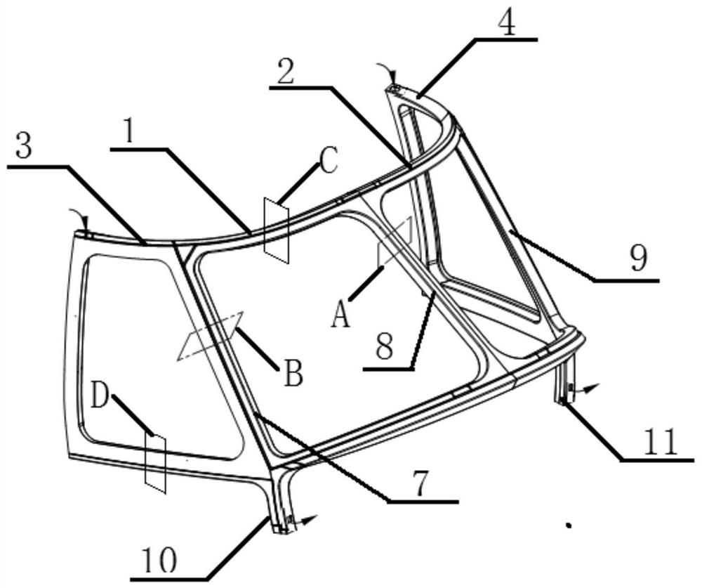
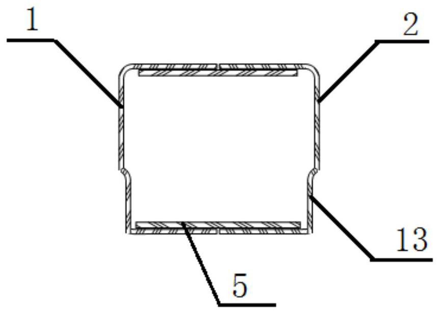
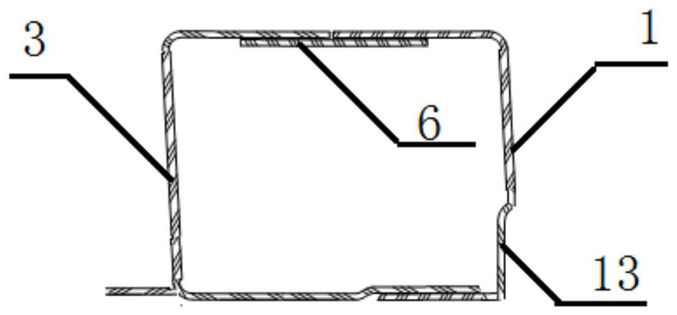
A supporting frame for an aircraft, comprising: a first windshield frame whose profile is "P" shaped; a second windshield frame whose profile is "P" shaped and one side of which is spliced ​​with one side of the first windshield frame to form a windshield frame; The windshield skeleton formed by splicing the windshield skeleton and the second windshield skeleton is in the shape of "Yuan"; the outline of the first side window frame is "P" shaped, and one side of the first windshield skeleton is spliced ​​with the side away from the second windshield skeleton; wherein, The protruding part of the first windshield frame is spliced ​​with the protruding part of the first side window frame to form a first leg; One side of the windshield frame is spliced; wherein, the protruding part of the second windshield frame is spliced ​​with the protruding part of the second side window frame to form a second leg; wherein, the first windshield frame, the second windshield frame, the first side window frame and The frame of the second side window is made of composite material, and is integrally formed by vacuum bag forming method.

Description

Technical field[0001]The application belongs to the technical field of aircraft support frame structure design, and specifically relates to an aircraft support frame.Background technique[0002]As the rigid support structure of the aircraft nose cockpit cover, the aircraft support frame is designed to transmit the flight load of the nose and its own inertial load. On the one hand, it interacts with the front skin, side skin, and bottom skin of the nose. The top skin is connected, and it needs to provide support for the skin that is connected to it to shape the skin; on the other hand, windshield glass, side-view glass and top-view glass must be installed on it to form a relatively closed space. And the external environment can be observed through the installed glass.[0003]Currently, aircraft support skeletons mostly use parts with |-shaped, L-shaped, and C-shaped sections to combine and assemble to form the lumen structure of the support skeleton, which is used to transmit load and sh...

Claims


Application Information

Patent Timeline
Patent Type & Authority Patents(China)
IPC IPC(8): B64C1/00
CPCB64C1/00B64C2001/0072
Inventor 王军杨东雷范光华陶国敏郑俊峰徐冬瑞
Owner CHINA HELICOPTER RES & DEV INST
Why Eureka
Try Eureka