
Plastic tube bending device

A bending device and a technology for plastic pipes, which are applied in the field of plastic products, can solve the problems of poor quality, complicated operation and large volume of manual pipe bending, and achieve the effects of simple structure, convenient operation and convenient use.

Inactive Publication Date: 2019-02-15
芜湖市崇兴乐塑胶有限公司
View PDF2 Cites 3 Cited by
  • Summary
  • Abstract
  • Description
  • Claims
  • Application Information

AI Technical Summary

Problems solved by technology

[0002] Plastic pipes have been widely used in daily life. In the actual installation process, the use occasions of plastic pipes are more complicated. Some occasions require straight pipes, and some occasions require bent pipes. Currently, there are few types of elbow joints commonly used. , cannot meet the needs of actual use. Therefore, in the actual installation process, workers will manually bend pipes according to the needs of on-site installation, and the quality of manual pipe bending is poor. There are also large-scale pipe bending machines in the industry, but these equipment volume It is large and complicated to operate, suitable for large quantities of pipe bending, so the industry needs a plastic pipe bending device with simple structure, easy operation, and suitable for small places to solve the problems faced by the industry

Method used


Image

  • Plastic tube bending device
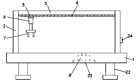
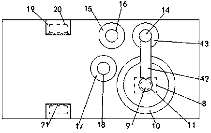
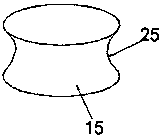
  • Plastic tube bending device
  • Plastic tube bending device

Examples


Embodiment Construction

[0020] The following will clearly and completely describe the technical solutions in the embodiments of the present invention with reference to the accompanying drawings in the embodiments of the present invention. Obviously, the described embodiments are only some of the embodiments of the present invention, not all of them. All other embodiments obtained by persons of ordinary skill in the art based on the embodiments of the present invention belong to the protection scope of the present invention.

[0021] According to an embodiment of the present invention, a plastic pipe bending device is provided.

[0022] Such as Figure 1-3 As shown, the plastic pipe bending device according to the embodiment of the present invention includes a base 1, a support column 2 and a cross bar 3, the top of the base 1 is symmetrically provided with the support columns 2 on both sides, and the support columns 2 on both sides The crossbar 3 is provided between the top ends of the crossbar 3, a...


PUM


Abstract

The invention discloses a plastic tube bending device which comprises a base, support columns and a cross bar. The two side edges of the top end of the base are symmetrically provided with the supportcolumns, the cross bar is arranged between the top ends of the support columns on the two sides, the bottom end of the cross bar is provided with a sliding groove, the bottom end of the sliding groove is provided with a slider matched with the sliding groove, the bottom end of the slider is provided with a telescopic rod, the bottom end of the telescopic rod is provided with a clamping jaw, and one side edge of the bottom end of the interior of the base is provided with a motor; an output shaft at the bottom end of the motor is connected with a third rotating shaft, the top end of the third rotating shaft penetrates through the top end of the base, a fixed wheel is arranged at the position, corresponding to the third rotating shaft, of one side edge of the top end of the base, the insideof the fixed wheel is of a hollow structure, the top end of the rotating shaft is located inside the fixed wheel, and the outer side of the top end of the third rotating shaft is provided with a firstconnecting sleeve matched with the third rotating shaft; and the height of the top end of the first connecting sleeve is larger than the height of the top end of the fixed wheel, and one side edge ofthe first connecting sleeve is provided with a connecting rod, and a connecting wheel is arranged at the bottom end of the side, far away from the first connecting sleeve, of the connecting rod.

Description

technical field [0001] The invention relates to the technical field of plastic products, in particular to a plastic pipe bending device. Background technique [0002] Plastic pipes have been widely used in daily life. In the actual installation process, the use occasions of plastic pipes are more complicated. Some occasions require straight pipes, and some occasions require bent pipes. Currently, there are few types of elbow joints commonly used. , cannot meet the needs of actual use. Therefore, in the actual installation process, workers will manually bend pipes according to the needs of on-site installation, and the quality of manual pipe bending is poor. There are also large-scale pipe bending machines in the industry, but these equipment volume It is relatively large and complicated to operate, and is suitable for large-scale pipe bending. Therefore, the industry needs a plastic pipe bending device with simple structure, convenient operation, and suitable for use in sm...

Claims


Application Information

Patent Timeline
Patent Type & Authority Applications(China)
IPC IPC(8): B29C53/08B29C53/84B29C53/80
CPCB29C53/083B29C53/80B29C53/84
Inventor 肖崇涛
Owner 芜湖市崇兴乐塑胶有限公司
Learn More