A metal positioning type cutting mechanism

A cutting mechanism and positioning technology, which is applied to metal processing equipment, shearing devices, cutters for shearing machines, etc. The effect of adjustment

Active Publication Date: 2021-03-19
东台市高科技术创业园有限公司
View PDF5 Cites 0 Cited by
  • Summary
  • Abstract
  • Description
  • Claims
  • Application Information

AI Technical Summary

Problems solved by technology

[0002] At present, metal plates or blocks sometimes need to be cut. The existing ones need to be cut with a cutting knife, but the existing cutting is all fixed on the knife seat, and the cutting knife cannot be carried out on the knife seat. Floating and telescopic, different processing situations may require different cutting depths. If the cutting knife cannot be floating and socketed, the range of use and flexibility will be greatly limited. The present invention needs to provide a metal cutting mechanism that can be retractable and floating

Method used


Image

  • A metal positioning type cutting mechanism
  • A metal positioning type cutting mechanism
  • A metal positioning type cutting mechanism

Examples


Embodiment Construction

[0019] The content of the present invention will be further described in detail below in conjunction with the accompanying drawings.

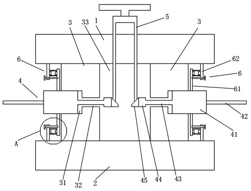
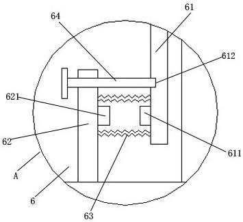
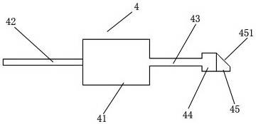
[0020] Such as Figures 1 to 4 As shown, a metal positioning cutting mechanism includes an upper splint 1, a lower splint 2, a connecting ring 3, a driving column 5, a cutting assembly 4, and a pressing mechanism 6; the upper splint 1 and the lower splint 2 are parallel up and down respectively Setting; the connecting ring 3 is installed between the upper splint 1 and the lower splint 2; the inside of the connecting ring 3 is provided with a drive chamber 33; the surrounding of the connecting ring 3 is evenly provided with a plurality of telescopic grooves 31; The cutting assembly 4 includes a cutting knife 42, a telescopic block 41, and a drive rod 43; a telescopic block 41 is respectively radially telescopically installed in the telescopic slot 31 of the connecting ring 3; the outer side of the telescopic block 41 is installed with a cutting ...


PUM


Abstract

The invention discloses a metal positioning type cutting mechanism. The metal positioning type cutting mechanism comprises an upper clamping plate, a lower clamping plate, a connecting ring, a drive column, a cutting assembly and a resisting mechanism. According to the metal positioning type cutting mechanism disclosed by the invention, a positioning screw rotates, extends out and draws back on apositioning ring, and is resisted and locked in a positioning ring slot of a resisting ring, so that a locking structure for the positioning ring and the resisting ring is formed, and therefore, connecting stability is prevented from being affected by unexpected tiny rotation of a telescopic block.

Description

technical field [0001] The invention relates to a metal positioning type cutting mechanism. Background technique [0002] At present, metal plates or blocks sometimes need to be cut. The existing ones need to be cut with a cutting knife, but the existing cutting is all fixed on the knife seat, and the cutting knife cannot be carried out on the knife seat. Floating and telescopic, different processing conditions may require different cutting depths. If the cutting knife cannot be floating and socketed, the range of use and flexibility will be greatly limited. The present invention needs to provide a metal cutting mechanism that can be stretched and floated. Contents of the invention [0003] Aiming at the shortcomings of the above-mentioned prior art, the problem to be solved by the present invention is to provide a metal cutting mechanism with stable connection and telescopic floating. [0004] In order to solve the above problems, the technical scheme that the present in...

Claims


Application Information

Patent Timeline
Patent Type & Authority Patents(China)
IPC IPC(8): B23D35/00
CPCB23D35/005
Inventor 孙颖
Owner 东台市高科技术创业园有限公司
Why Eureka
Try Eureka