
Deformation correcting method

A technology for welding deformation and thin plates, which is applied in the field of deformation correction and can solve problems such as affecting the overall aesthetics of the locomotive and wide tolerance range of the flatness of the correction position.

Active Publication Date: 2019-02-15
CRRC DALIAN CO LTD
View PDF8 Cites 1 Cited by
  • Summary
  • Abstract
  • Description
  • Claims
  • Application Information

AI Technical Summary

Problems solved by technology

[0004] However, since the flame correction is spot heating at the welding deformation position, it will not only leave uneven spots on the correction position, which will affect the overall aesthetics of the locomotive, and the tolerance range of the flatness of the correction position is relatively large

Method used


Image

  • Deformation correcting method
  • Deformation correcting method
  • Deformation correcting method

Examples


Embodiment Construction

[0042] In order to make the purpose, technical solutions and advantages of the present invention clearer, the technical solutions in the embodiments of the present invention will be described in more detail below with reference to the drawings in the preferred embodiments of the present invention. In the drawings, the same or similar reference numerals denote the same or similar components or components having the same or similar functions throughout. The described embodiments are some, but not all, embodiments of the invention. The embodiments described below by referring to the figures are exemplary and are intended to explain the present invention and should not be construed as limiting the present invention. Based on the embodiments of the present invention, all other embodiments obtained by persons of ordinary skill in the art without creative efforts fall within the protection scope of the present invention. Embodiments of the present invention will be described in deta...


PUM

PropertyMeasurementUnit
Diameteraaaaaaaaaa
Plate thicknessaaaaaaaaaa

Abstract

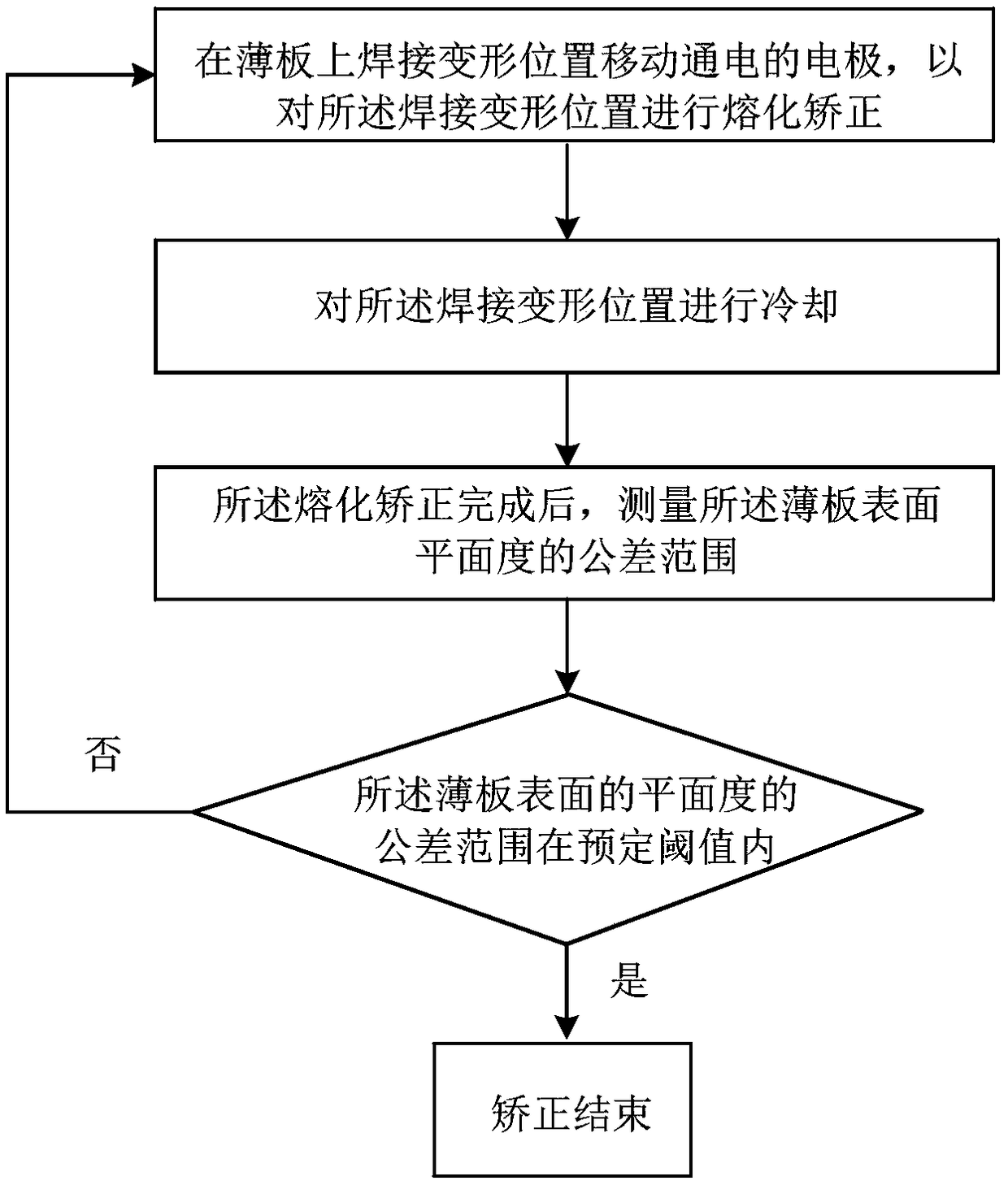
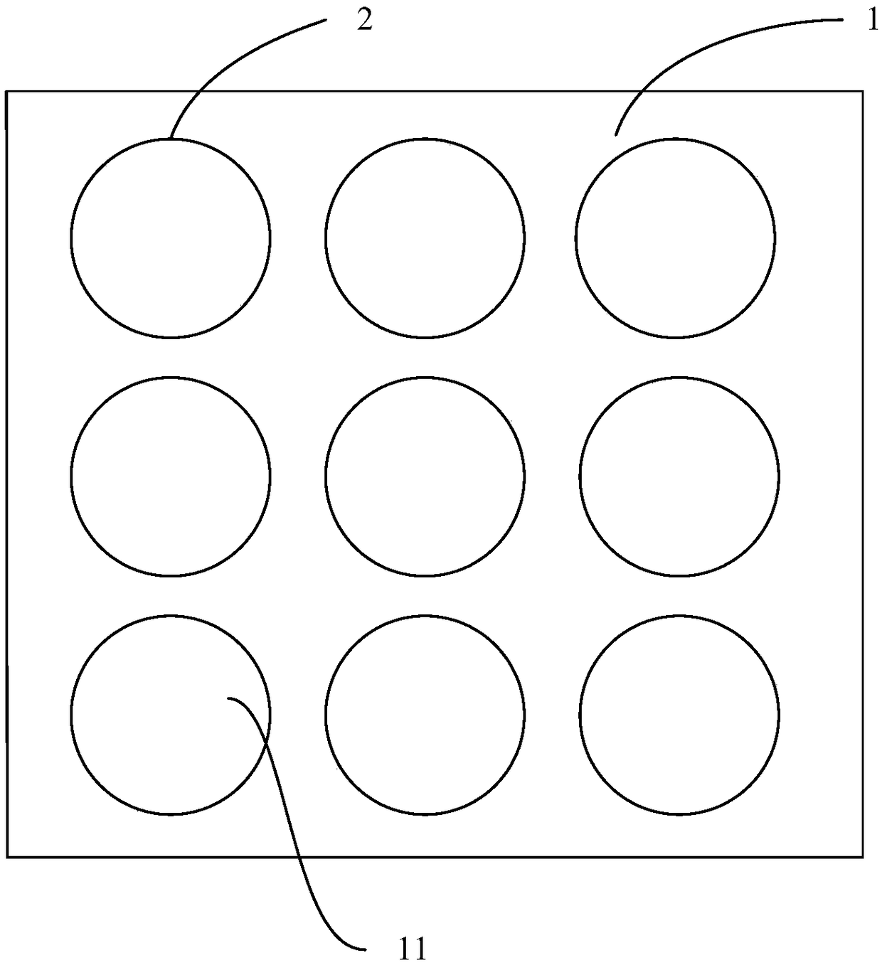
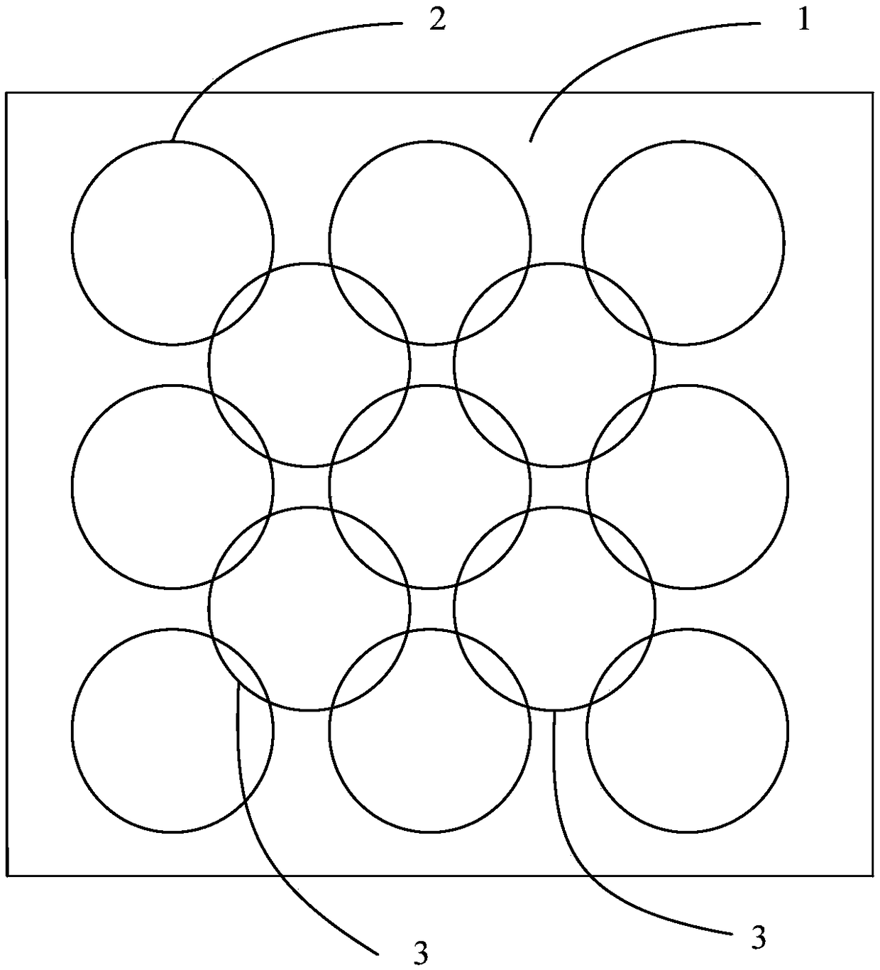
The invention provides a deformation correcting method. The deformation correcting method comprises the steps that S1, an electrode which is energized is moved at a welding deformation position on a thin plate to perform melting correction on the welding deformation position, and a movement trajectory of the electrode when performing the melting correction is at least one circle; and S2, after themelting correction is completed, the tolerance range of the flatness of the surface of the thin plate is measured, and the steps S1 and S2 are repeated until the tolerance range of the flatness of the surface of the thin plate is within a predetermined threshold value. The occurrence of irregular spots at the correction position is effectively avoided, and the tolerance range of the flatness of the correction position is further reduced, so that the surface of the thin plate is smoother and more attractive.

Description

technical field [0001] The invention relates to the technical field of vehicle welding, in particular to a deformation correction method. Background technique [0002] With the development of the international railway industry and the improvement of the level of railway equipment, high-speed heavy-duty railways and lightweight equipment have become inevitable requirements for entering the international railway market, and this will undoubtedly bring great challenges to controlling the welding deformation of the plates used in railway equipment. , that is, under the condition of constant material, the light weight of railway equipment requires that the thickness of the plate used in railway equipment be reduced accordingly, and the thin plate is more prone to welding deformation due to the input of a large amount of welding heat in a large amount of welding work. , so that the skin is prone to certain concave-convex deformation at the position away from the skeleton. Therefo...

Claims


Application Information

Patent Timeline
IPC IPC(8): B21D1/12
CPCB21D1/12
Inventor 马宋明辉王明山张卓王龙于静
Owner CRRC DALIAN CO LTD
Learn More