
Tapered roller bearing assembling device and working method thereof

A tapered roller bearing and sleeve-fitting technology, which is applied to bearing components, shafts and bearings, mechanical equipment, etc., can solve the problem of the large number of lift plates and transfer plates, no quick riveting device, and increased roller friction damage. and other problems, to achieve the effect of saving labor costs, convenient feeding, and rapid riveting

Inactive Publication Date: 2019-02-12
山东龙本轴承科技有限公司
View PDF1 Cites 1 Cited by
  • Summary
  • Abstract
  • Description
  • Claims
  • Application Information

AI Technical Summary

Problems solved by technology

[0002] When the existing tapered rollers and bearings are combined, although in some steps, there have been instruments that can be used, but there are still some problems in the use of the existing matching instruments. For example, some instruments are After installing the tapered roller, the bearing cage and the inner sleeve, manual operation is required to put the unriveted initial product into the mold, and when it is put into the mold, the position needs to be calibrated, and then placed under the press , operate the press to press down, after pressing, take out the mold and the product, and then manually separate the product from the mold, which needs to be removed by force, which is time-consuming and laborious
However, there is no fast riveting device for direct riveting after installing the cage, tapered roller and inner sleeve.
[0003] Chinese patent document CN 106736448 B discloses a tapered roller bearing assembly device. The principle of the feeding device is that the lifting plate is driven by the cylinder to rise to the same height as the transfer plate, and multiple lifting plates are matched with the transfer plate one by one. The rollers are finally transferred to the unloading plate, and in the process of transferring from one stage to another, the friction of the rollers is relatively large, which has a certain impact on the subsequent application; and the height of the hopper is fixed. If the position of the hopper is too high, the lifting The number of sets of plates and transfer plates is small, which can reduce friction, but the position of the hopper is too high and there is a problem of inconvenient discharge; if the hopper is low, the number of sets of lift plates and transfer plates will be more, resulting in friction on the rollers increased damage

Method used


Image

  • Tapered roller bearing assembling device and working method thereof
  • Tapered roller bearing assembling device and working method thereof
  • Tapered roller bearing assembling device and working method thereof

Examples


Embodiment 1

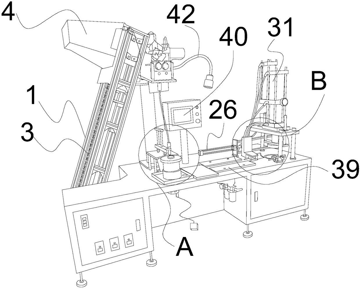
[0039] Referring to the accompanying drawings, the present invention provides a tapered roller bearing assembly device, which includes an operating platform, and is characterized in that it also includes a feeding device, a feeding device, an operating panel, a transmission device, and a riveting device;

[0040] The feeding device is installed on one side of the console and includes a support frame 1, a feeding motor 2 and a hopper 4; the bottom of the support frame 1 is fixed with a feeding motor 2, and the output shaft of the feeding motor is connected to a gear. The gear is connected with the hopper 4 through the chain 3; the hopper 4 is installed on the support frame 1, and the support frame 1 is installed at an inclination here, and a slide rail is installed on the support frame 1, and the bottom end of the hopper is connected with a The chute, under the action of the feeding motor 2, the feeding motor 2 rotates positively and negatively, and the chain 3 drives the hopper...

Embodiment 2

[0054] The working method of the above-mentioned tapered roller bearing assembly device includes the following steps:

[0055] Step 1: Feeding: After the manual switch controls the feeding motor 2 to feed, turn on the corresponding switch of the controller, the feeding cylinder acts, and transfers the tapered rollers to the feeding section. The photoelectric switch 18 monitors the number of rollers in the feeding trough. When the number of rollers is too much, the feedback signal controller, the controller transmits a signal to the feeding cylinder, and the feeding cylinder stops moving and stops feeding; at the same time, the rollers directly fall into the feeding trough;

[0056] Step 2: Cutting the material and forming the initial product: through the two oppositely rolling rollers 19 set at an inclination, the rollers are moved in the direction of the material tube 10, and the fan blades 16 are rotated to screen the direction of the rollers. When the bottom surface of the ...


PUM


Abstract

The invention provides a tapered roller bearing assembling device. The tapered roller bearing assembling device comprises an operation platform, and further comprises a feeding device, a discharging device, an operation board, a transmission device and a riveting device. Meanwhile, the invention further provides a working method of the tapered roller bearing assembling device. Through a feeding section, a roller is lifted one time and conveyed to the next assembling part, the abrasion to the roller is reduced, a hopper can be lifted and lowered through the effects of a motor and a chain, and discharging is facilitated. Through limiting at two positions, it is guaranteed that the hopper stops moving at the upper position and the lower position. Through the transmission device, an initial product is conveyed to the riveting device, the riveting device presses down automatically, in the whole assembling process, artificial participation is less, human cost is saved, the working efficiencyis improved, rapid riveting of a holder, the tapered roller and an inner sleeve is realized, and the precision of a product is guaranteed.

Description

technical field [0001] The invention belongs to the technical field of bearing production equipment, in particular to a tapered roller bearing assembly device and a working method thereof. Background technique [0002] When the existing tapered rollers and bearings are combined, although in some steps, there have been instruments that can be used, but there are still some problems in the use of the existing matching instruments. For example, some instruments are After installing the tapered roller, the bearing cage and the inner sleeve, manual operation is required to put the unriveted initial product into the mold, and when it is put into the mold, the position needs to be calibrated, and then placed under the press , operate the press to press down, after pressing, take out the mold and the product, and then manually separate the product from the mold, which needs to be removed by force, which is time-consuming and laborious. However, there is no fast riveting device for ...

Claims


Application Information

Patent Timeline
Patent Type & Authority Applications(China)
IPC IPC(8): F16C43/06F16C43/04
CPCF16C43/065F16C43/04
Inventor 刘吉泽王文斌孙宗凯王凤勇刘勇刘占强孙福耕宫志华
Owner 山东龙本轴承科技有限公司
Learn More