
High-end plastic thin film conveying device

A plastic film and conveying device technology, which is applied in the directions of transportation and packaging, sending objects, thin material processing, etc., can solve the problems of no direct connection of the film conveyor, tearing or wrinkling of the film, increasing labor intensity of personnel, etc., and achieves a simple structure , reduce manpower and material resources, and achieve a high degree of automation

Inactive Publication Date: 2019-02-12
广州雅隆自动化设备有限公司
View PDF0 Cites 4 Cited by
  • Summary
  • Abstract
  • Description
  • Claims
  • Application Information

AI Technical Summary

Problems solved by technology

[0002] In the process of film processing, the film needs to be stretched. However, most of the existing film tensions are manually pulled to the pinch wheel. This operation is easy to tear or wrinkle the soft film. , produce unnecessary waste of film, and increase the labor intensity of personnel
Moreover, the current film cutting operation needs to use multiple motors at the same time, and there is a big disadvantage that there is no direct connection with the film conveyor, which needs to be improved.

Method used


Image

  • High-end plastic thin film conveying device
  • High-end plastic thin film conveying device
  • High-end plastic thin film conveying device

Examples


Embodiment Construction

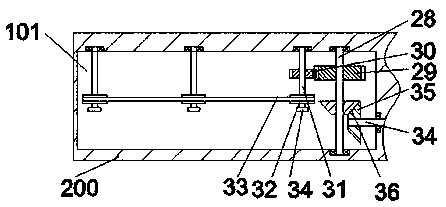
[0023] like Figure 1-5As shown, a high-end plastic film conveying device of the present invention includes an outer frame 200 and a conveying device located in the first cavity 100 with the opening on the right side of the outer frame 200 facing right and a conveying device located in the outer frame 200. 200 is the cutting device in the sliding cavity 101 on the left side, the top wall of the first cavity 100 is fixed with a gear housing 201, and the gear housing 201 has an installation cavity 103, and the front and rear end walls of the first cavity 100 can be Rotation is provided with a first rotating shaft 71, a mounting plate 73 and a first pulley 11 behind the mounting plate 73 are fixed on the first rotating shaft 71, and a front and rear pulley is connected to the far right side of the mounting cavity 103. The extended second rotating shaft 23, the front extension end of the second rotating shaft 23 is connected to the front end wall of the installation cavity 103 in ...


PUM


Abstract

The invention discloses a high-end plastic thin film conveying device comprising an outer rack, a conveying device and a cutting device. The conveying device is located in a first cavity which is formed in the right side of the outer rack and is provided with a rightward opening, and the cutting device is located in a sliding cavity in the left side of the outer rack; a gear housing is fixed to the top wall of the interior of the first cavity, a mounting cavity is formed in the gear housing, a first rotating shaft is rotatably arranged in the front and rear end walls of the first cavity, the first rotating shaft is fixedly provided with a mounting disc and a first belt wheel located behind the mounting disc, a second rotating shaft extending front and back is connected to the rightmost side of the interior of the mounting cavity in a matched manner, the front side extending end of the second rotating shaft is connected with the end wall of the front side of the mounting cavity in a rotary fit manner, the rear side extending section of the second rotating shaft is in power connection with a first motor fixedly arranged in the end wall of the back side of the mounting cavity, and thesecond rotating shaft is fixedly provided with a second belt wheel connected to the first belt wheel through a first belt.

Description

technical field [0001] The invention relates to film processing, in particular to a high-end plastic film conveying device. Background technique [0002] In the process of film processing, the film needs to be stretched. However, most of the existing film tensions are manually pulled to the pinch wheel. This operation is easy to tear or wrinkle the soft film. , produce unnecessary waste of film, and increase the labor intensity of personnel. Moreover, the current film cutting operation needs to use multiple motors at the same time and has no direct connection with the film conveyor, which has great disadvantages and needs to be improved. Contents of the invention [0003] Aiming at the deficiencies of the above-mentioned technologies, the present invention proposes a high-end plastic film conveying device. [0004] A high-end plastic film conveying device of the present invention comprises an outer frame, a conveying device located in the first cavity on the right side o...

Claims


Application Information

Patent Timeline
IPC IPC(8): B65H20/16B65H23/26B65H35/06B65H35/00B65H29/16
CPCB65H20/16B65H23/26B65H29/16B65H35/0086B65H35/06B65H2301/5115
Inventor 韦红生
Owner 广州雅隆自动化设备有限公司
Learn More