Connecting method and device of spinning machinery

A technology of jointing device and jointing method, which is applied in the field of jointing of spinning machinery and its device, and can solve problems such as jointing failure and yarn breakage

Inactive Publication Date: 2002-10-23
MURATA MASCH LTD
View PDF3 Cites 3 Cited by
  • Summary
  • Abstract
  • Description
  • Claims
  • Application Information

AI Technical Summary

Problems solved by technology

[0004] In the above-mentioned piecing method, the lead-out timing of the standard yarn introduced into the twisting device is earlier than the supply timing of feeding the sliver into the inside of the spinning nozzle by the re-driving of the rear roller, so that there is a problem that the constituent yarn The fibers of the sliver cannot be entangled on the standard yarn, resulting in joint failure, or only a small amount of fibers constituting the front end of the thin sliver are entangled on the standard yarn, forming a thin joint, and yarn breakage occurs again

Method used


Image

  • Connecting method and device of spinning machinery
  • Connecting method and device of spinning machinery
  • Connecting method and device of spinning machinery

Examples


Embodiment Construction

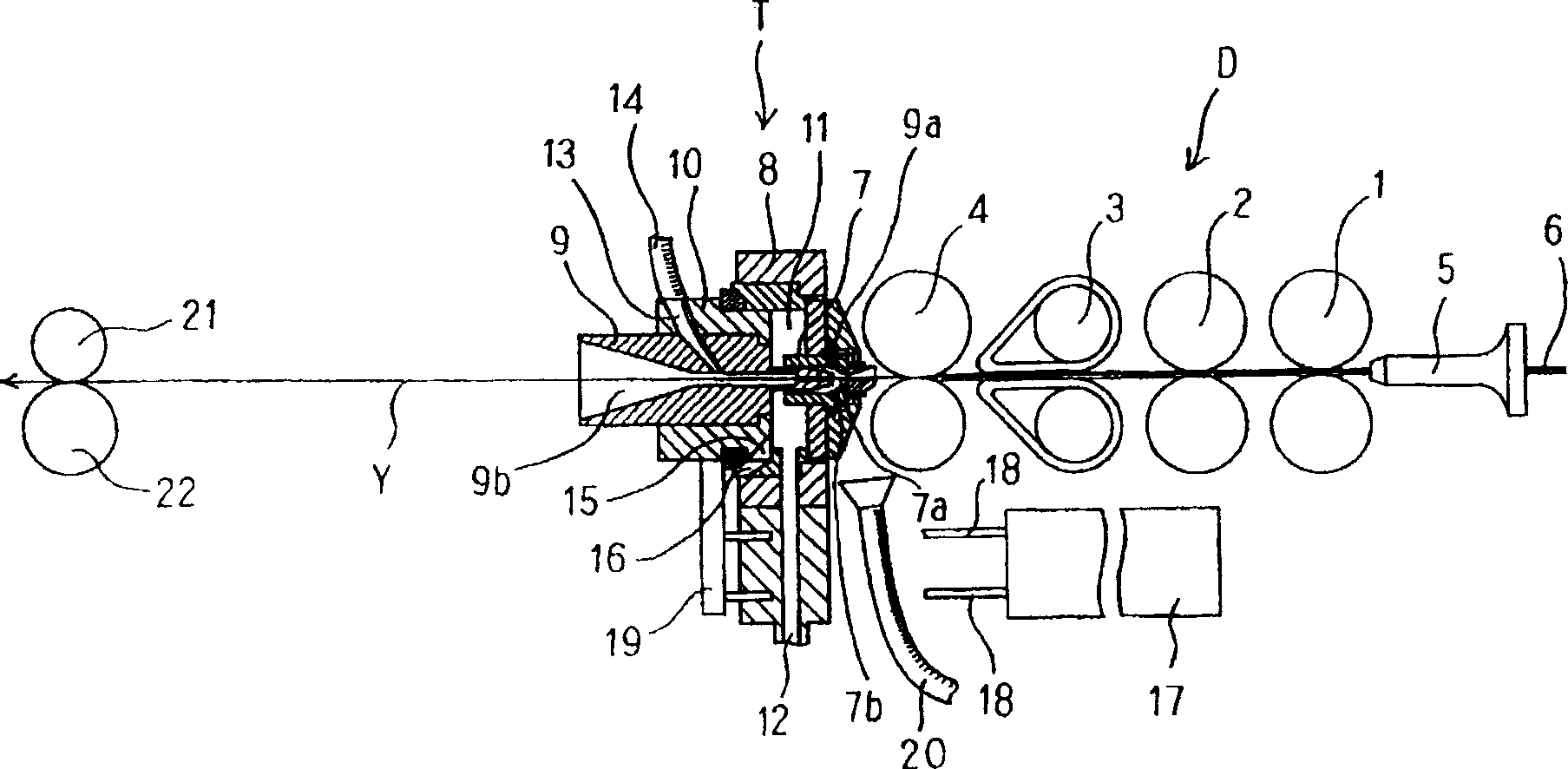
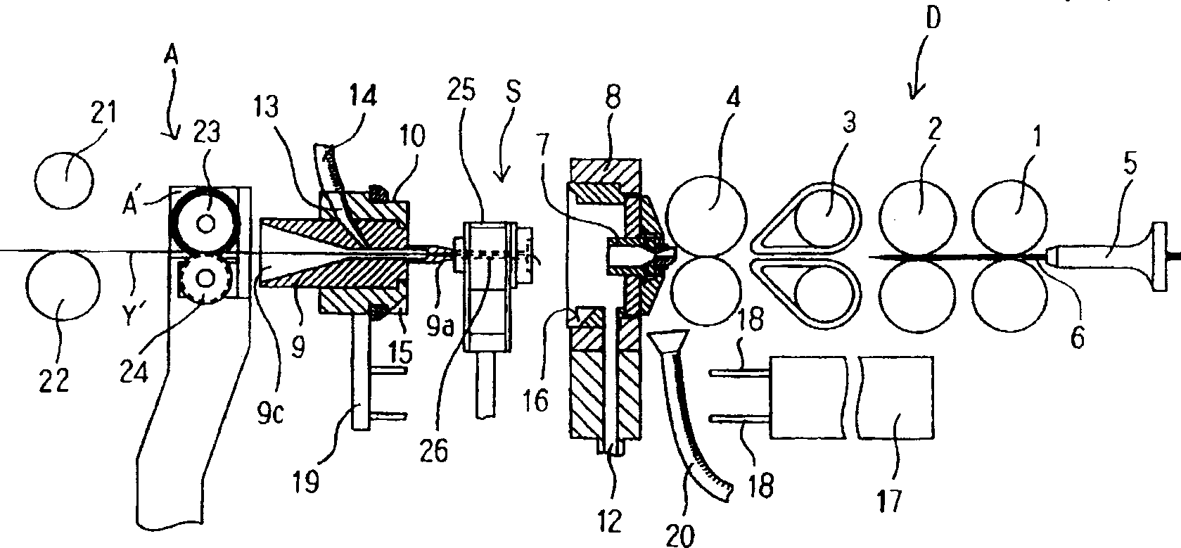
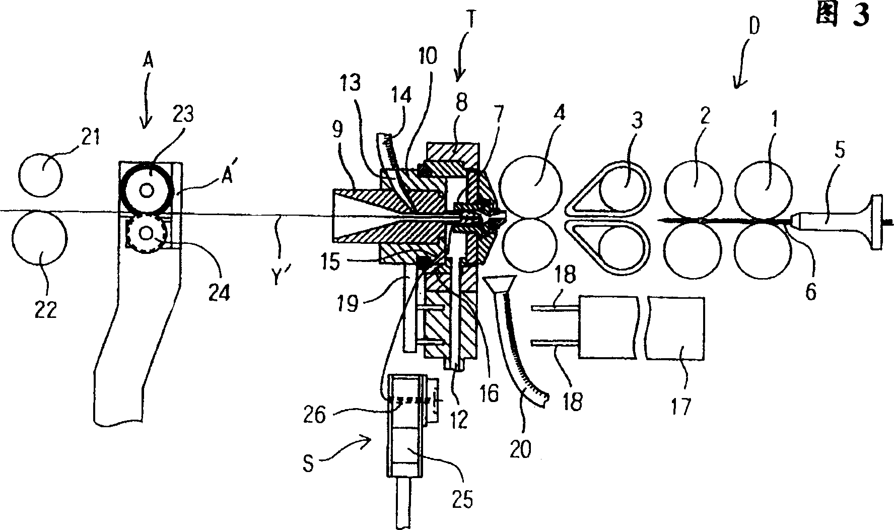
[0018] First, use figure 1 -6. The spinning machine as an example of the piecing method applied to the spinning machine will be described.

[0019] D is a traction device, and a traction device with four pairs of rollers is shown as an example. The traction device D is composed of four pairs of rollers, that is, a rear roller 1, a side roller 2, a middle roller 3 on which a dragon belt is erected, and a front roller 4. 5 is a creel, and the sliver 6 inserted into the creel 5 and supplied to the drawing device D is supplied to the drawing device D and stretched, and then supplied to the twisting device described below to form a yarn.

[0020] The twisting device T mainly includes: an air spinning nozzle 7 that forms a swirling airflow by jetting compressed air, a nozzle holder 8 that supports the nozzle, and a spindle with a through hole 9b that places its front end 9a inside the air spinning nozzle 9. (yarn guide tube) 9, and a support member 10 for supporting the spindle. ...


PUM


Abstract

The splicing method related to the present invention is to keep the standard yarn Y' discharged from the sliver inlet 7c of the stopped twisting device T outside the twisting device T and the sliver 6 transferred by the restarted traction device, and then use The twisting device works, and the above-mentioned sliver is supplied to the twisting device, so that the fibers constituting the sliver are wound on the standard yarn drawn out from the twisting device. Therefore, the success rate of piecing can be improved without strictly adjusting the timing of pulling out the standard yarn Y' introduced into the twisting device T and the timing of supplying the sliver 6 to the twisting device T.

Description

technical field [0001] The invention relates to a splicing method and a device thereof for connecting broken yarns in a spinning machine. Background technique [0002] In the prior art, the following spinning machine piecing method and its device have been disclosed, that is, the yarn end on the take-up side is introduced into the twisting device of the spinning machine, and thereafter by re-spinning, the yarn end is spun again. In the yarn process, the end of the sliver introduced into the twisting device and the end of the yarn (hereinafter referred to as standard yarn) introduced into the take-up side of the twisting device are connected. [0003] In the above-mentioned piecing method of the spinning machine, the timing of drawing out the standard yarn introduced into the twisting device and the timing of supplying the sliver to the inside of the spinning nozzle by redriving the back roller are very important to improve the success rate of piecing. of. [0004] In the a...

Claims


Application Information

Patent Timeline
Patent Type & Authority Patents(China)
IPC IPC(8): D01H15/00
CPCD01H15/002D01H15/00
Inventor 平尾修西邑正彦
Owner MURATA MASCH LTD
Why Eureka
Try Eureka