
Spark plug

A technology for spark plugs and insulators, which is applied in the field of spark plugs, can solve the problems of carbon burning of insulators, etc., and achieve the effects of improving fouling resistance, simple structure, and ensuring fouling resistance

Active Publication Date: 2019-02-05
NGK SPARK PLUG CO LTD
View PDF5 Cites 2 Cited by
  • Summary
  • Abstract
  • Description
  • Claims
  • Application Information

AI Technical Summary

Problems solved by technology

As a result, the carbon deposited on the insulator is burned

Method used


Image

  • Spark plug
  • Spark plug
  • Spark plug

Examples


Embodiment

[0075] The present invention is explained in more detail by way of examples, but the present invention is not limited to the examples.

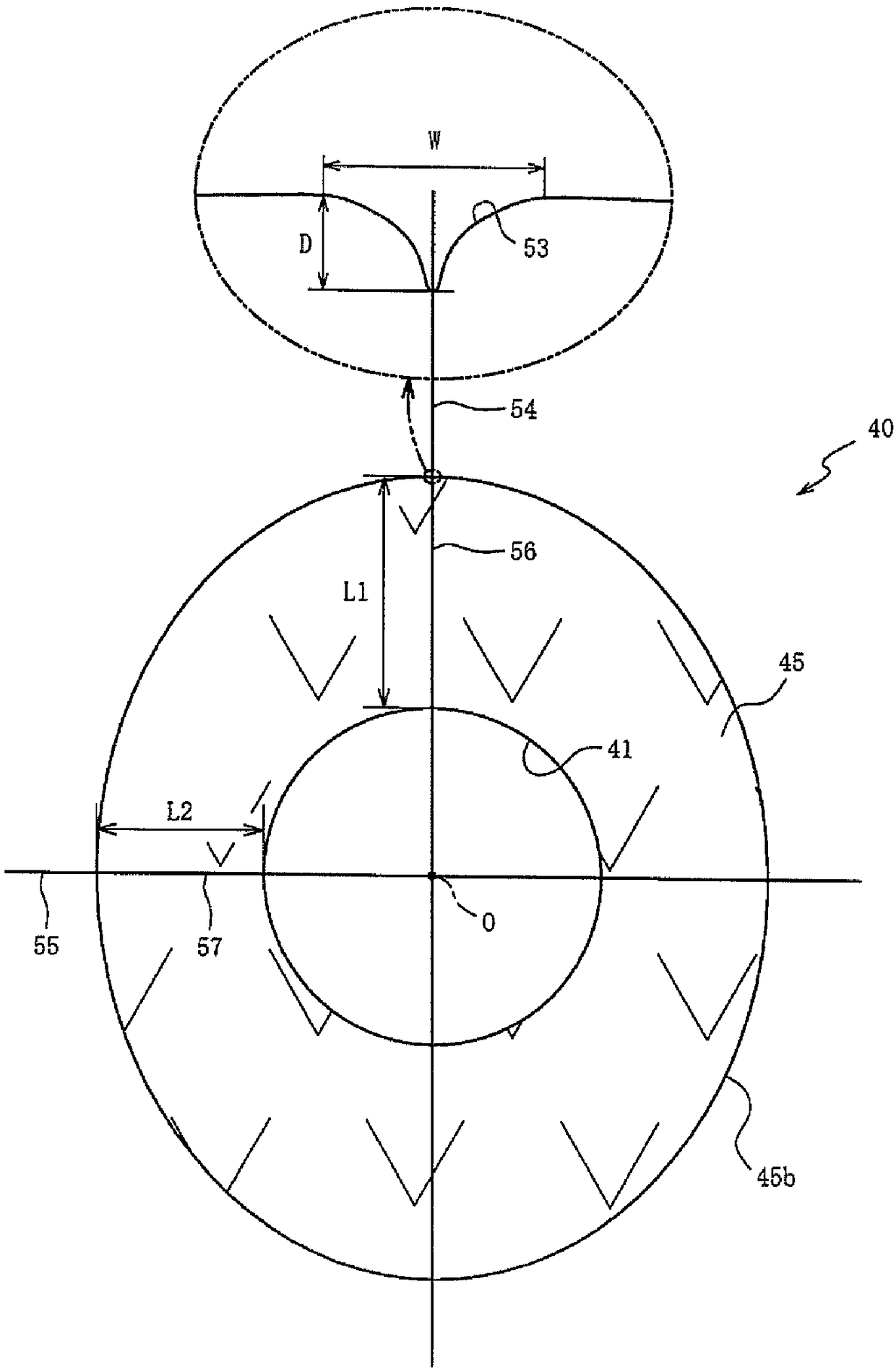
[0076] Samples 1 to 30 of the spark plug 10 incorporating various insulators 40 were produced, and the fouling properties and withstand voltage were evaluated. As shown in Table 1, in samples 1 to 30, the arithmetic mean roughness (Ra) of the outer peripheral surface 45b of the front end portion 45 of the insulator 40, the depth D of the concave portion 53, the width W of the concave portion 53, the number of the concave portion 53, the second The value (length ratio) obtained by dividing the length L2 of the region 57 by the length L1 of the first region 56 and the position (angle) of the concave portion 53 with respect to the first region 56 are different. In addition, the length L of the recessed part 53 was set to 15 mm in all the samples 1-30. In addition, in the sample in which the plurality of recesses 53 were formed, the recesses wer...


PUM


Abstract

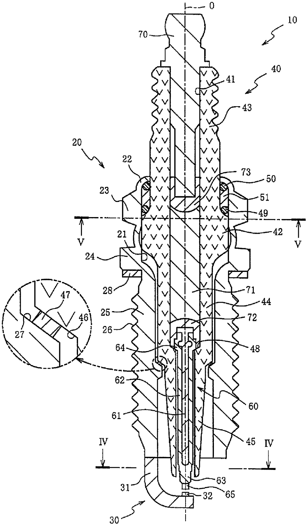
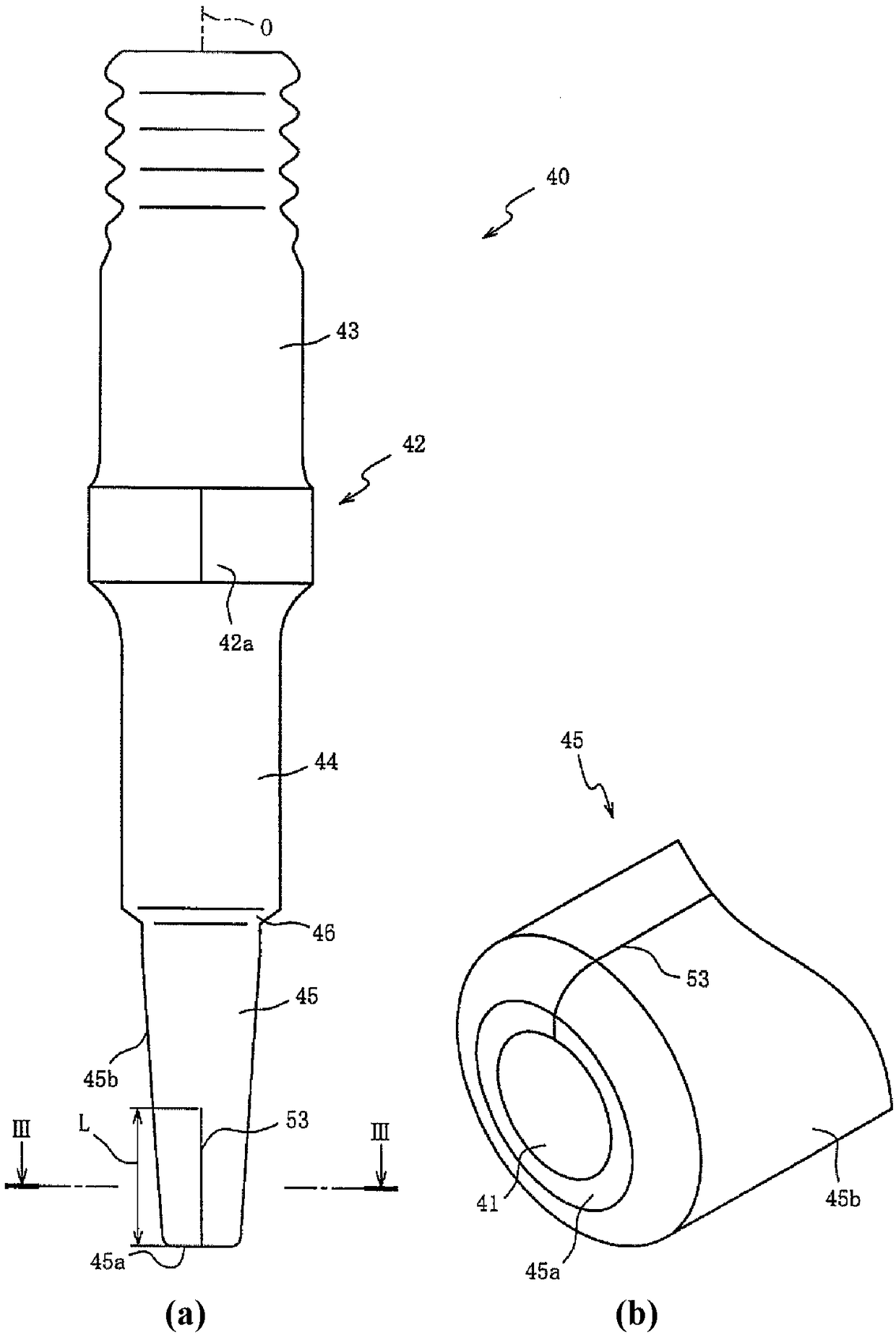
Provided is a spark plug for which contamination resistance can be ensured with a simple structure. An insulator having a step part formed on the outer circumferential surface thereof has a center electrode disposed in a shaft hole. A tubular main fitting having a step part and a shelf part formed on the inner circumferential surface thereof is disposed radially outward from the insulator. The tippart of the insulator is positioned further toward the tip side of the insulator than is the step part. On the tip part, the arithmetic average roughness in the circumferential direction of the outercircumferential surface is 0.5 [mu]m or less. On at least a portion of the end surface and the outer circumferential surface of the tip part, a recess having a depth of 3-20 [mu]m is provided extending from the tip side to the rear-end side.

Description

technical field [0001] The present invention relates to a spark plug, and relates to a spark plug capable of securing fouling resistance. Background technique [0002] In general, a spark plug is such that a metal body to which a ground electrode is connected is insulated and holds a center electrode via an insulator. The spark plug generates a spark discharge between the ground electrode and the center electrode in the combustion chamber of the internal combustion engine to ignite the air-fuel mixture. However, carbon generated due to incomplete combustion, etc. is deposited on the surface of the insulator and the insulation resistance is reduced. When a voltage is applied When the voltage is lower than the required voltage (the voltage at which spark discharge occurs), spark discharge will no longer occur. Therefore, various techniques for preventing fouling of insulators due to carbon deposition have been developed. [0003] For example, Patent Document 1 discloses a te...

Claims


Application Information

Patent Timeline
Patent Type & Authority Applications(China)
IPC IPC(8): H01T13/20
CPCH01T13/20H01T13/14H01T13/06H01T13/32
Inventor 井笹纯平中野成治黑野启一田中邦治横山裕吉田治树近藤俊
Owner NGK SPARK PLUG CO LTD
Learn More