Flow path switching valve

A flow path switching and flow path technology, applied to valve devices, multi-way valves, cocks including cut-off devices, etc., can solve problems such as pressure drop

Inactive Publication Date: 2019-02-05
DENSO CORP +1
View PDF7 Cites 0 Cited by
  • Summary
  • Abstract
  • Description
  • Claims
  • Application Information

AI Technical Summary

Problems solved by technology

In addition, the pressing force of the spool may decrease due to variation or deterioration of each component.

Method used


Image

  • Flow path switching valve
  • Flow path switching valve
  • Flow path switching valve

Examples


no. 1 approach

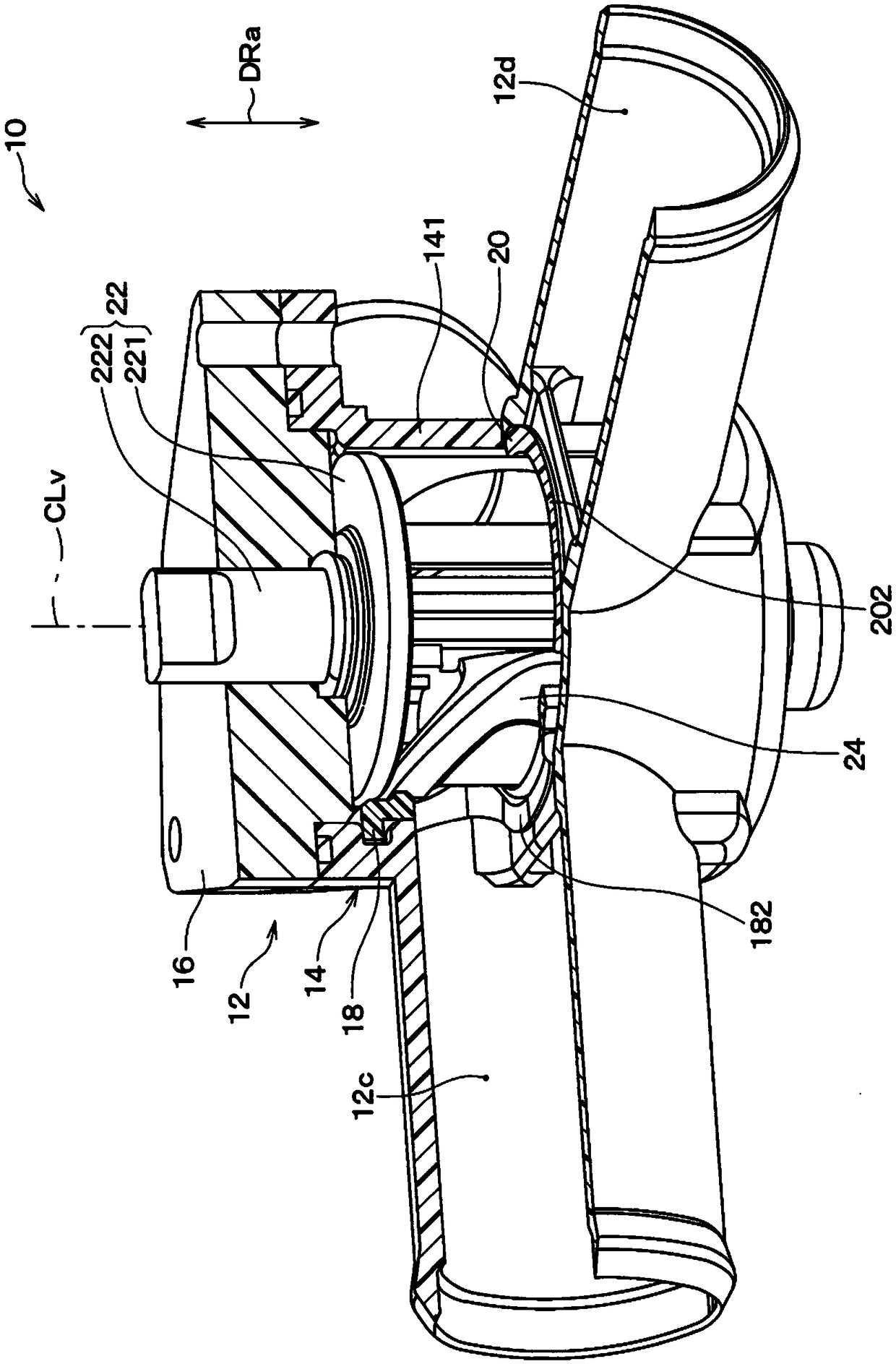
[0031] Such as figure 1 and figure 2 As shown, the channel switching valve 10 is a rotary valve that switches the channel through which fluid flows. Specifically, the channel switching valve 10 is a rotary three-way valve. The fluid flowing through the channel switching valve 10 , that is, the circulating fluid is specifically a liquid. The channel switching valve 10 includes a valve main body 12 , a controller member 22 , and a packing member 24 .

[0032] The valve main body portion 12 includes a valve body member 14 , a cover member 16 and two sealing members 18 , 20 . For example, the valve body member 14, the cover member 16, and the two sealing members 18 and 20 are all made of resin.

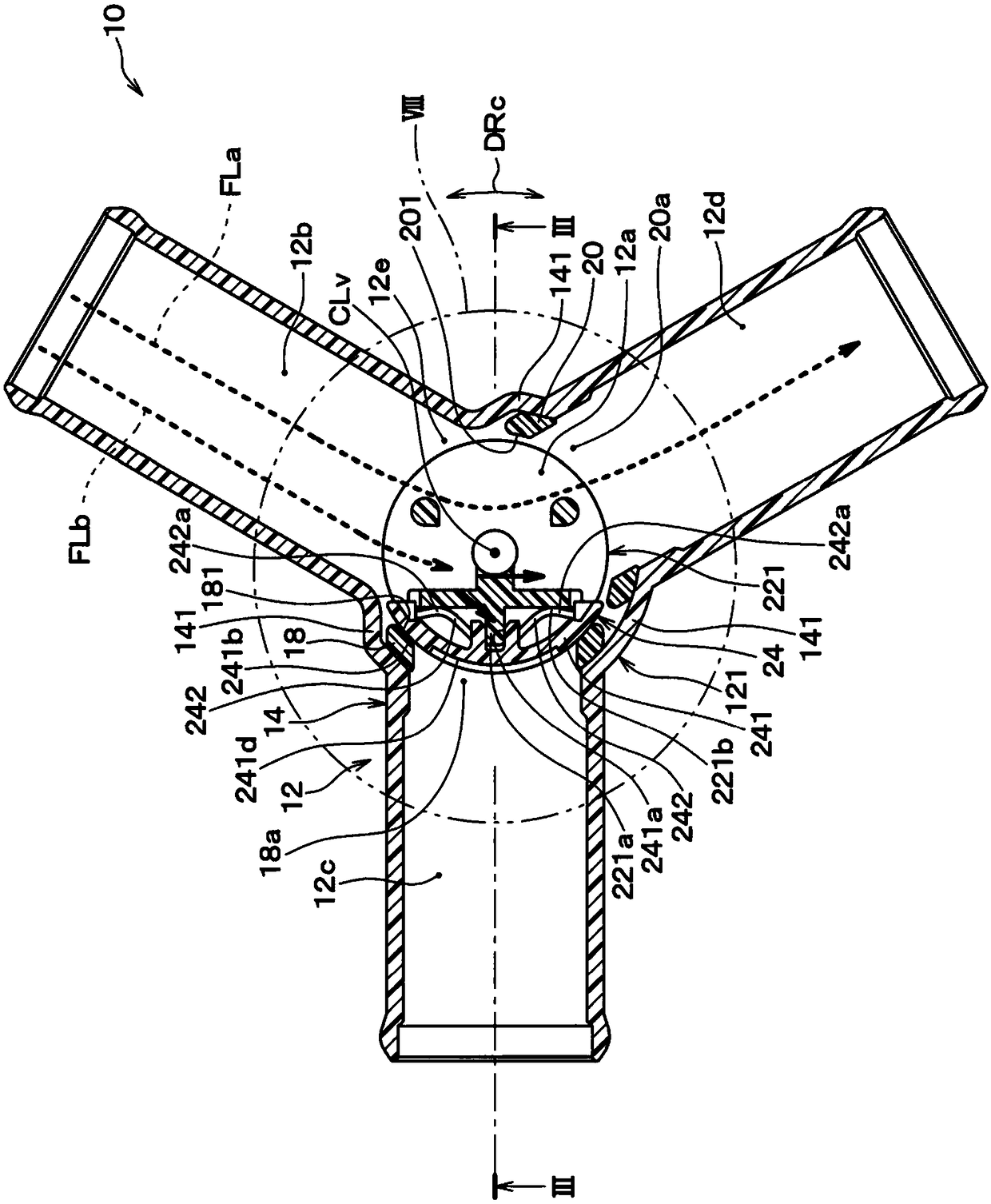
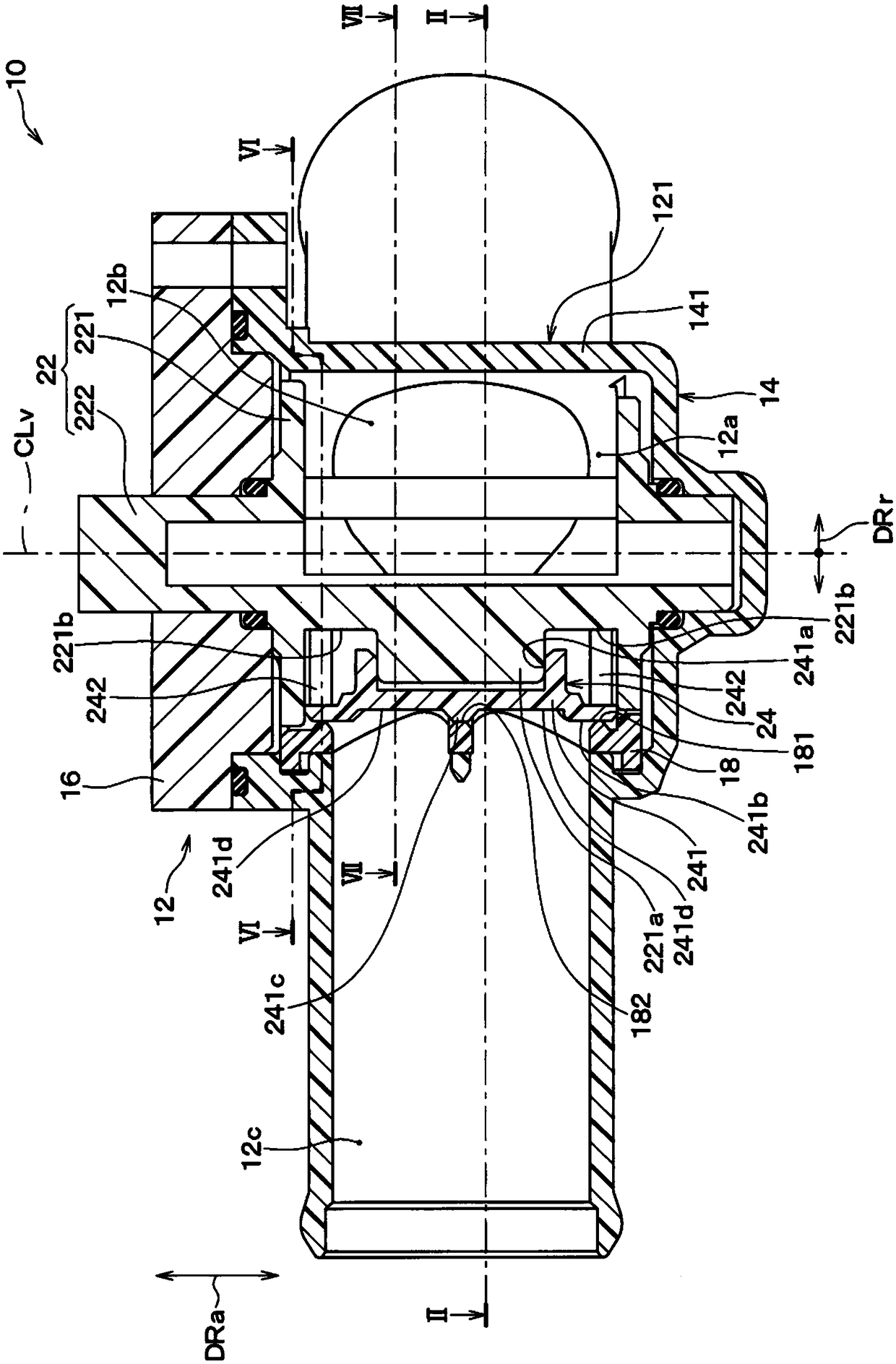
[0033] Such as figure 2 and image 3 As shown, a valve chamber 12 a , an inflow hole 12 b , a first outflow hole 12 c , and a second outflow hole 12 d are formed in the valve main body 12 . Specifically, the valve chamber 12 a is mainly formed in the valve body member 14 in the v...


PUM


Abstract

A flow path switching valve is provided with: a rotating section (221) rotating about the valve axis (CLv); a packing section (241) supported on the rotating section so as not to be rotatable relativethereto; and a valve body section (12). The valve body section has formed therein a valve chamber (12a) in which the rotating section and the packing section are accommodated, an inflow hole (12b), and outlet holes (12c, 12d). The valve body section has a valve chamber outer peripheral section (121) surrounding the valve chamber around the valve axis. The outlet holes have outlet hole opening ends (18a, 20a) open to the valve chamber at locations on the valve chamber outer peripheral section. The valve chamber outer peripheral section has body seal sections (181, 201) extended so as to surround the outlet hole opening ends and exposed to the inside of the valve chamber. As the rotating section rotates, the packing section is positioned at a predetermined position at which the packing section closes an outlet hole opening end. When positioned at the predetermined position, the packing section is pressed against body seal sections in the radial direction (DRr) relative to the valve axisby the pressure of fluid within the valve chamber, the pressure being higher than pressure within the outlet hole.

Description

[0001] Cross-references to related applications [0002] This application is based on the JP Patent application number 2016-120627 for which it applied on June 17, 2016, The description content is incorporated in this application by reference. technical field [0003] The present invention relates to a flow path switching valve for switching or opening and closing a flow path through which a fluid flows. Background technique [0004] As such a channel switching valve, for example, the channel switching valve described in Patent Document 1 is conventionally known. The channel switching valve described in this Patent Document 1 is a rotary three-way valve. The flow path switching valve of Patent Document 1 includes: a valve main body having a valve chamber communicating with an inlet port and two outlet ports; a valve body made of an elastic body; and a valve holder which The spool is supported. The spool alternately closes the two outlet ports by rotating together with the...

Claims


Application Information

Patent Timeline
Patent Type & Authority Applications(China)
IPC IPC(8): F16K5/04F16K11/076
CPCF16K5/04F16K11/076F16K11/085F16K11/0856F16K11/0876F01P2007/146F16K11/0853
Inventor 铃木珠城桥村信幸清水忠夫金泽启史
Owner DENSO CORP
Why Eureka
Try Eureka