Electrical control cabinet

A technology for electrical control cabinets and cabinets, which is applied to electrical components, electrical equipment shells/cabinets/drawers, cabinets/boxes/drawer parts, etc. Internal circuit short circuit etc.

Active Publication Date: 2019-02-05
重庆大潼电气设备有限公司
View PDF18 Cites 2 Cited by
  • Summary
  • Abstract
  • Description
  • Claims
  • Application Information

AI Technical Summary

Problems solved by technology

[0002] The electrical control cabinet is a cabinet made of steel to protect the normal operation of components. According to the requirements of electrical wiring, switchgear, measuring instruments, protective appliances and auxiliary equipment are assembled in closed or semi-closed metal cabinets or on the screen. Its layout should meet the requirements of the normal operation of the power system and facilitate maintenance. The electrical control cabinets are divided into indoor installation and outdoor installation, and most of them are side-opening cabinet doors. Among them, the electrical control cabinet installed outdoors needs to be opened in rainy days. During the inspection, the side-opening cabinet door can easily cause rainwater to splash into the cabinet, causing a short circuit in the circuit in the cabinet. At the same time, the switchgear in the electrical control cabinet is easy to catch fire when a short circuit occurs. If it is not prevented, it will easily cause a fire. In addition, the existing outdoor electrical control cabinets are mostly installed on the wall or on the utility poles. When the switchgear in the cabinet needs to be repaired, the maintenance personnel need to carry out climbing operations, which makes it difficult to place various tools used by the maintenance personnel. In view of this, we propose An electrical control cabinet

Method used


Image

  • Electrical control cabinet
  • Electrical control cabinet
  • Electrical control cabinet

Examples


Embodiment 1

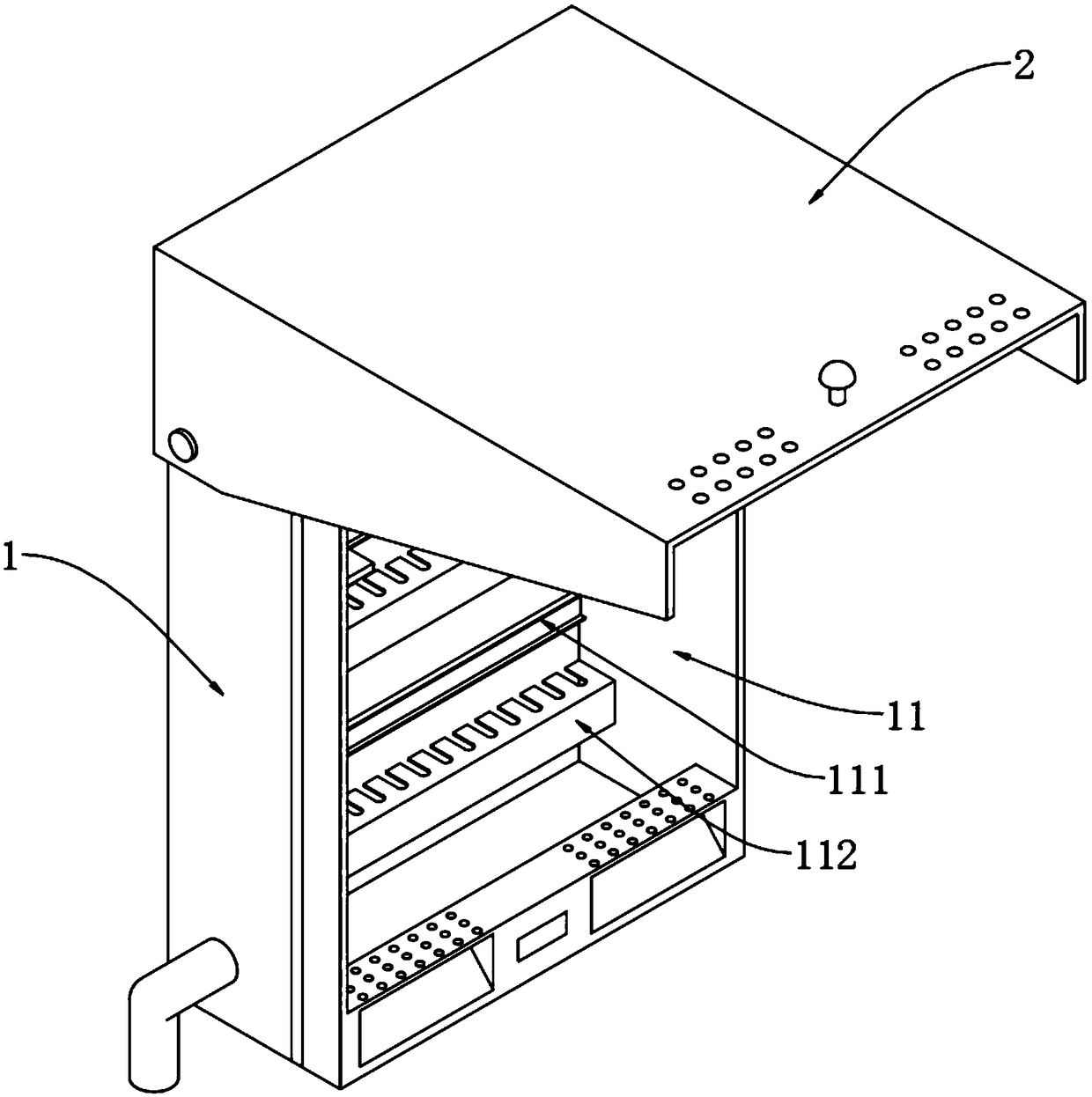
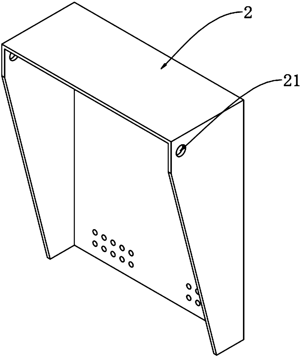
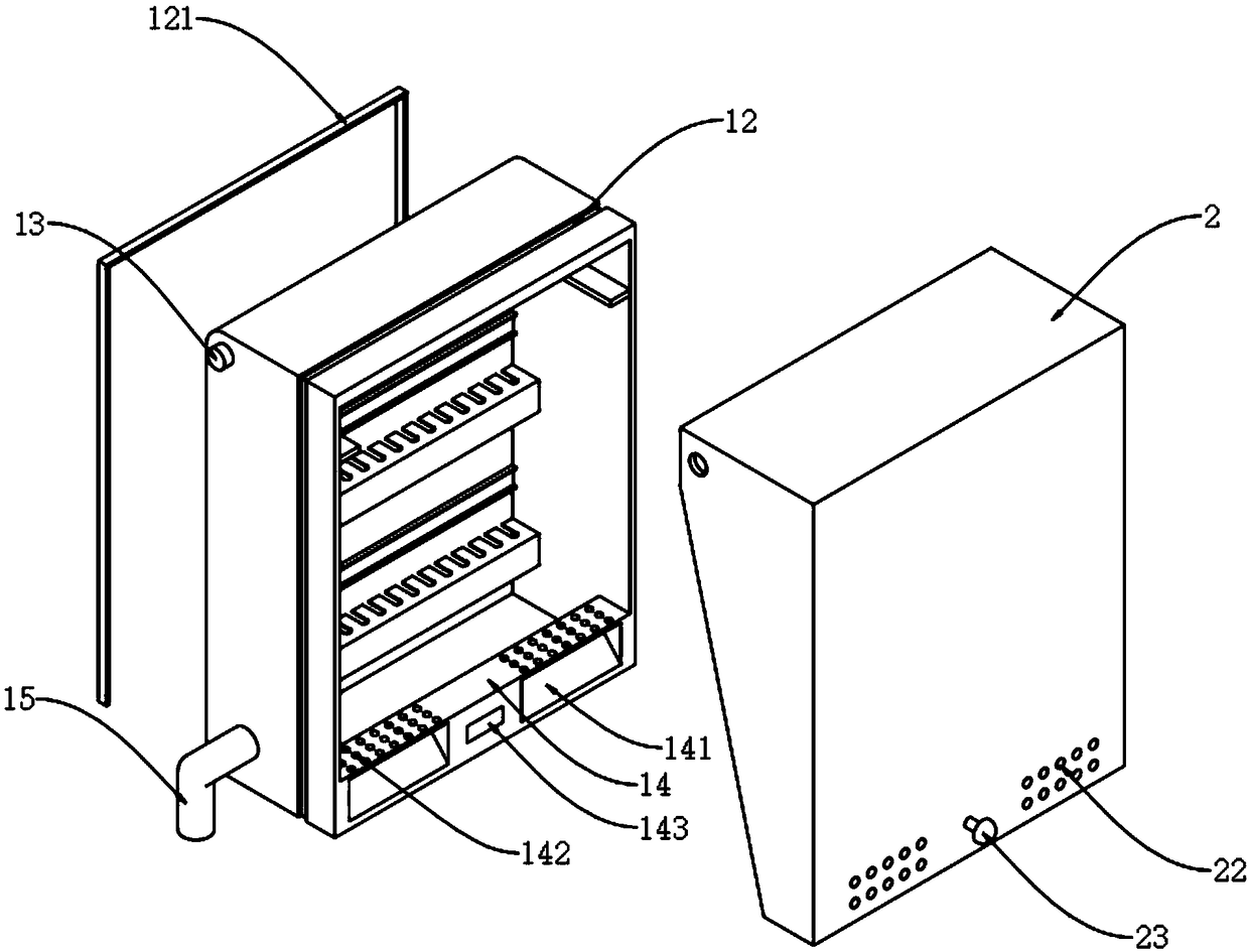
[0033] An electrical control cabinet, such as figure 1 , figure 2 , image 3 and Figure 4 As shown, including the cabinet body 1, the cabinet body 1 is provided with a cavity 11, and the outer surface of the cabinet body 1 is provided with a long groove 12, and a sealing strip 121 is embedded in the long groove 12, and the bottom edge of the cavity 11 A bottom column 14 is provided at the bottom column 14, and a pair of symmetrically distributed inclined openings 141 are provided at the front end of the bottom column 14. Several through holes 142 connected with the inclined openings 141 are opened at the top of the bottom column 14, and the front end of the cabinet body 1 is hinged with a surface. Cover 2.

[0034] In this embodiment, a number of mounting plates 111 for installing switchgear are installed on the bottom of the cavity 11 through screws, and a cable management plate 112 for hiding connecting cables is installed under the mounting plates 111 through screws. ...

Embodiment 2

[0038] In the specific operation, since the switchgear in the electrical control cabinet is easy to catch fire when a short circuit occurs, if it is not prevented, it is very easy to cause a fire. Therefore, a C-shaped partition is tightly welded at the top of the cavity 11. Plate 16, the top of partition 16 is overlapped with storage device 3, as a kind of preferred embodiment, as Figure 5 , Image 6 and Figure 7 As shown, the storage device 3 includes a storage box 31 slidably connected to the cavity 11, a film 32 overlapped in the storage box 31, and a pressure frame 33 slidably connected to the storage box 31. The storage box 31 is a cuboid structure, and the storage box 31 There is a storage cavity 311 inside, and the bottom end of the storage cavity 311 is provided with a bottom opening 312 in a rectangular shape. Slots 313 are provided at the middle positions of the two sides.

[0039] In this embodiment, the film 32 is a PE film, and the pressure frame 33 is locat...

Embodiment 3

[0043] In the specific operation, since the various tools used by maintenance personnel are not easy to place when maintaining the switchgear in the cabinet, therefore, a placement platform 4 is provided at the bottom of the cabinet body 1. As a preferred embodiment, as Figure 8 , Figure 9 , Figure 10 and Figure 11 As shown, the placement platform 4 includes a placement box 41 and a number of sliding plates 42 installed in the placement box 41. The placement box 41 is a box structure with a hollow top, and the interior of the placement box 41 is provided with horizontal spacers 411. The rear end surface of the bar 411 and the rear end surface of the storage box 41 are provided with a chute 412, and the right front end of the storage box 41 is provided with a turntable 413, and the turntable 413 is provided with a rotary hole 4131, and a rotating shaft 414 is sleeved in the rotary hole 4131. The top of the rotating shaft 414 is tightly welded with the cabinet body 1, and ...


PUM


Abstract

The invention relates to the technical field of electrical equipment, and especially relates to an electrical control cabinet. The electrical control cabinet includes a cabinet body; the cabinet bodyis provided with a cavity; the outer surface of the cabinet body is provided with a long groove; a sealing strip is embedded in the long groove; the edge at the bottom of the cavity is provided with abottom column; the front of the bottom column is provided with a pair of inclined openings in symmetrical distribution; the top of the bottom column is provided with multiple through holes communicating with the inclined openings; and the front end of the cabinet body is in hinged joint with a face cover, so that rainwater can be kept out by the face cover and prevented from splashing in the cabinet body when the electrical control cabinet opens the face cover in rainy days. Through the arrangement of a storage device on the top of the cavity and the filling of a fire extinguishing layer in the storage device, a film can be melted by the high temperature of flames when switch equipment in the cabinet body is in short circuit and on fire, and therefore, the fire extinguishing layer can bespattered on the surface of the switch equipment, and fire extinguishing effects can be achieved; and through the arrangement of a placing platform at the bottom of the cabinet body, various maintenance tools and small parts can be placed on the placing platform when the switch equipment in the cabinet is maintained.

Description

technical field [0001] The invention relates to the technical field of electrical equipment, in particular to an electrical control cabinet. Background technique [0002] The electrical control cabinet is a cabinet made of steel to protect the normal operation of components. According to the requirements of electrical wiring, switchgear, measuring instruments, protective appliances and auxiliary equipment are assembled in closed or semi-closed metal cabinets or on the screen. Its layout should meet the requirements of the normal operation of the power system and facilitate maintenance. The electrical control cabinets are divided into indoor installation and outdoor installation, and most of them are side-opening cabinet doors. Among them, the electrical control cabinet installed outdoors needs to be opened in rainy days. During the inspection, the side-opening cabinet door can easily cause rainwater to splash into the cabinet, causing a short circuit in the circuit in the ca...

Claims


Application Information

Patent Timeline
Patent Type & Authority Applications(China)
IPC IPC(8): H05K5/02A62C3/16
CPCA62C3/16H05K5/0217H05K5/03
Inventor 陈建
Owner 重庆大潼电气设备有限公司
Why Eureka
Try Eureka