Gas distribution block, pneumatic system, pneumatic grain-discharging device and filter tank
A gas distribution and filter tank technology, which is applied in the field of pneumatic waste removal device and filter tank, pneumatic system and gas distribution block, which can solve the problems of operator burns, low efficiency and low output.
- Summary
- Abstract
- Description
- Claims
- Application Information
AI Technical Summary
Problems solved by technology
Method used
Image
Examples
no. 1 example
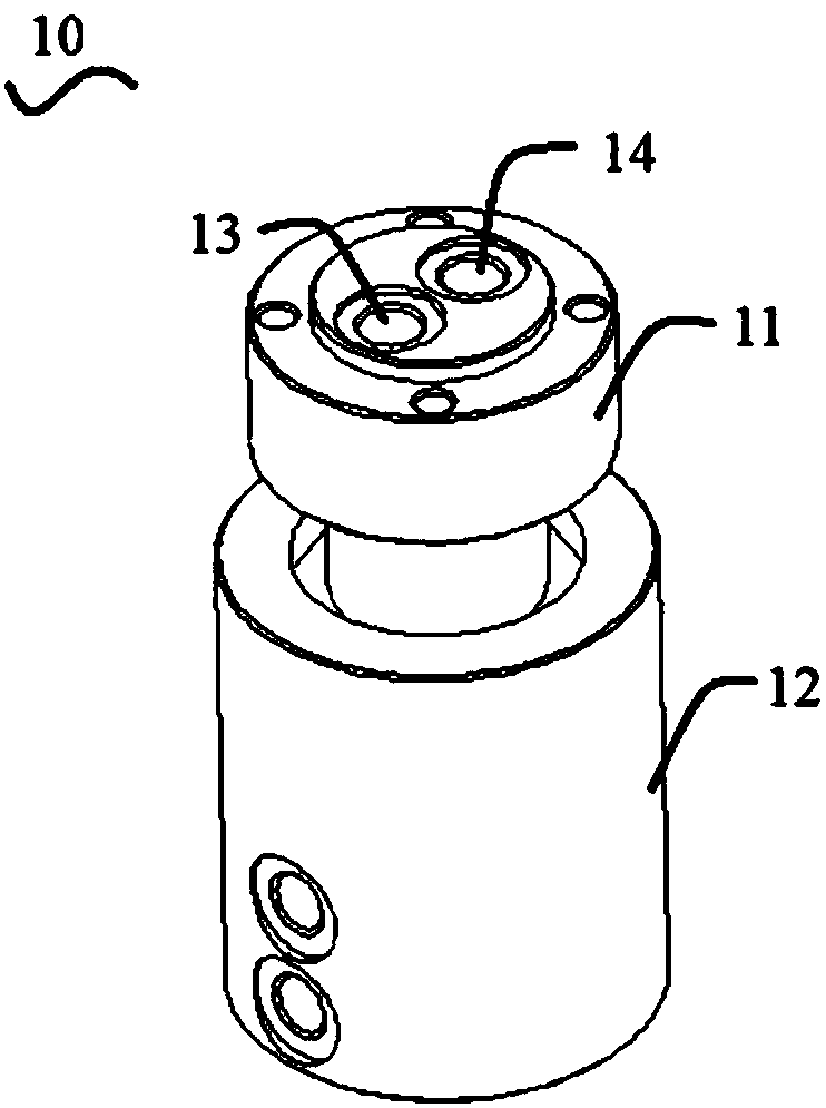
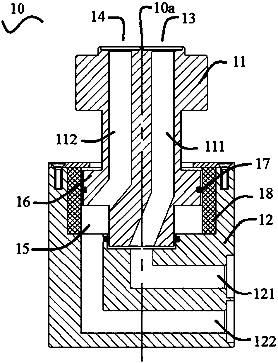
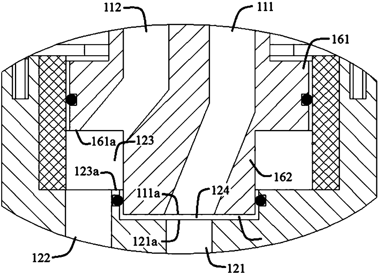
[0061] Such as Figure 1 to Figure 3 As shown, the first embodiment of the present invention provides a gas distribution block 10, the upper part of which has two air holes, and the two air holes are used to connect air intake equipment, such as an air compressor. Further, the gas distribution block 10 includes a first sub-block 11 and a second sub-block 12 that can rotate relative to each other. The first sub-block 11 includes two first air channels 111 and second air channels 112 that are not connected to each other. The interior of the second sub-block 12 includes two third air passages 121 and fourth air passages 122 which are not connected to each other. The shape of each airway can be linear or curved; it can be equal in diameter or variable in diameter; its axes can be in one plane or not in one plane. Such as figure 2 As shown, this embodiment provides an airway that is easy to process, but the form of the airway of the present invention is not limited thereto.
[...
no. 2 example
[0078] The second embodiment of the present invention provides a pneumatic system 20 , which includes a cylinder 21 , and a cylinder body 214 of the cylinder 21 has a first chamber 212 and a second chamber 213 divided by a piston 211 . The pneumatic system 20 also includes a gas distribution block.
[0079] Specifically, the gas distribution block is the gas distribution block 10 provided in the first embodiment of the present invention. That is, the gas distribution block 10 is provided with a first gas channel 13 and a second gas channel 14 that are not connected to each other. Further, the gas distribution block 10 includes a first sub-block 11 and a second sub-block 12 that can rotate relatively. A sub-block 11 includes two first air passages 111 and a second air passage 112 that are not connected to each other, and the second sub-block 12 includes two third air passages 121 and fourth air passages 122 that are not connected to each other. The first air channel 111 and th...
no. 3 example
[0086] Such as Figure 5 As shown, the third embodiment of the present invention provides a pneumatic waste removal device 30 , which includes a tiller arm 31 and a scraper assembly 32 connected below the tiller arm 31 .
[0087] Further, the pneumatic waste removal device 30 also includes the pneumatic system 20 provided by the second embodiment of the present invention, the pneumatic system 20 includes the cylinder 21, the cylinder body 214 of the cylinder 21 has the first chamber 212 and the second chamber 212 divided by the piston 211 Two chambers 213 . The pneumatic system 20 also includes the gas distribution block 10 provided by the first embodiment of the present invention. The first chamber 212 communicates with the first gas channel 13 , and the second chamber 213 communicates with the second gas channel 14 .
[0088] The gas distribution block 10 is the gas distribution block provided in the first embodiment of the present invention, which is provided with a first...
PUM
 Abstract
Description
Claims
Application Information
 - R&D
- Intellectual Property
- Life Sciences
- Materials
- Tech Scout
- Unparalleled Data Quality
- Higher Quality Content
- 60% Fewer Hallucinations
Browse by: Latest US Patents, China's latest patents, Technical Efficacy Thesaurus, Application Domain, Technology Topic, Popular Technical Reports.
© 2025 PatSnap. All rights reserved.Legal|Privacy policy|Modern Slavery Act Transparency Statement|Sitemap|About US| Contact US: help@patsnap.com


