A Broadband High Gain Patch Antenna with Low Profile

A patch antenna, high gain technology, applied in the direction of the connection of the antenna ground switch structure, the structure of the radiating element, etc., can solve the problems of reducing the antenna polarization diversity gain, increasing the complexity of the antenna, destroying the low profile characteristics, etc. The effect of polarization level, light weight, small radiation loss

Active Publication Date: 2021-03-16
SHENZHEN UNIV
View PDF2 Cites 0 Cited by
  • Summary
  • Abstract
  • Description
  • Claims
  • Application Information

AI Technical Summary

Problems solved by technology

[0004] However, there are some defects in the above-mentioned technologies: adding parasitic patches will increase the thickness of the antenna and destroy the low-profile characteristics; slotting on the patch can easily increase the cross-polarization level and reduce the polarization diversity gain of the antenna; Adding a complex impedance matching network, such as a quarter-wavelength impedance transformation section, will introduce additional transmission loss, reduce antenna efficiency, and increase the complexity of the antenna

Method used


Image

  • A Broadband High Gain Patch Antenna with Low Profile
  • A Broadband High Gain Patch Antenna with Low Profile
  • A Broadband High Gain Patch Antenna with Low Profile

Examples


Embodiment Construction
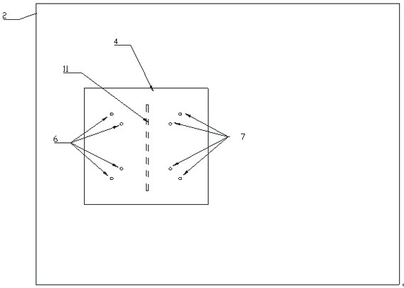
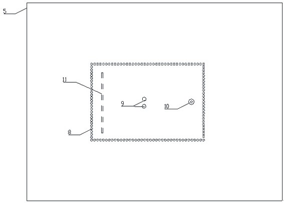
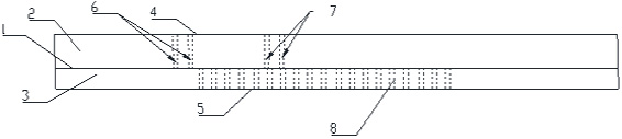
[0021] The key idea of ​​the present invention is that: the second metal base plate is connected to the first metal base plate through the third short-circuit component group to form a dielectric integrated waveguide structure that can significantly increase its impedance bandwidth and improve its radiation gain. By opening hollow slots on the first metal base plate and coupling and feeding the metal patch, the even mode can be suppressed, thereby reducing the level of cross polarization; by loading the fourth The short-circuit component group changes the current distribution and field distribution of the antenna in different resonance modes, so that two or more resonance modes are gathered to form a broadband; the first short-circuit component group and the second short-circuit component group are used to pair the The metal patch is short-circuit loaded to obtain a larger resonance size, which greatly improves the radiation gain of the antenna.

[0022] In order to describe t...


PUM


Abstract

The present invention provides a low-profile broadband high-gain patch antenna. The low-profile broadband high-gain patch antenna includes a metal patch, a first dielectric substrate, a first metal substrate, a second dielectric bottom plate, and a second metal bottom plate which are distributed from top to bottom; an elongated hollow slot is formed in the first metal bottom plate; the projectionof the center of the metal patch on the first metal bottom plate falls within the hollow slot; the metal patch is connected with the first metal bottom plate through two short-circuit component sets which are symmetrical to each other in terms of positions and shapes; and the second metal bottom plate is connected with the first metal bottom plate through the other two short-circuit component setsand a feed body. According to the low-profile broadband high-gain patch antenna, the plurality of short-circuit components are loaded so as to excite a plurality of working modes, and resonant frequencies of low-order modes are increased; since the electric field strength of high-order modes at positions where the short-circuit components are loaded is weak, the field distribution of the high-order modes is not affected, therefore, bandwidth is realized; and a dielectric integrated waveguide structure is introduced, so that the propagation of surface waves can be suppressed, and therefore, radiation efficiency can be improved, and gain can be increased; and the hollow slot suppresses even-number modes, and therefore, the level of cross polarization can be reduced.

Description

technical field [0001] The invention relates to a patch antenna, in particular to a wide-band high-gain patch antenna with a low profile. Background technique [0002] The concept of the microstrip patch antenna was first proposed in 1953, but it was not gradually developed until the 1970s. Due to its small size, light weight and low profile, microstrip patch antennas have been widely used in mobile communication systems, such as active integrated antennas, satellite navigation, satellite communications and radar. However, the traditional microstrip antenna has the disadvantages of relatively narrow bandwidth, high loss, low efficiency, and small power capacity, and its application is often limited. [0003] In response to the above problems, the predecessors proposed several technologies to improve the bandwidth of patch antennas, mainly including: adding additional parasitic radiation elements, loading slot structures of various shapes on the patch, adding broadband imped...

Claims


Application Information

Patent Timeline
Patent Type & Authority Patents(China)
IPC IPC(8): H01Q1/36H01Q1/38H01Q1/50
CPCH01Q1/36H01Q1/38H01Q1/50
Inventor 廖淑敏张晓黄冠龙袁涛吴琼森祝雷
Owner SHENZHEN UNIV
Why Eureka
Try Eureka