
Aero-engine high-speed rotating disk bolt drag reduction design method and rotating disk

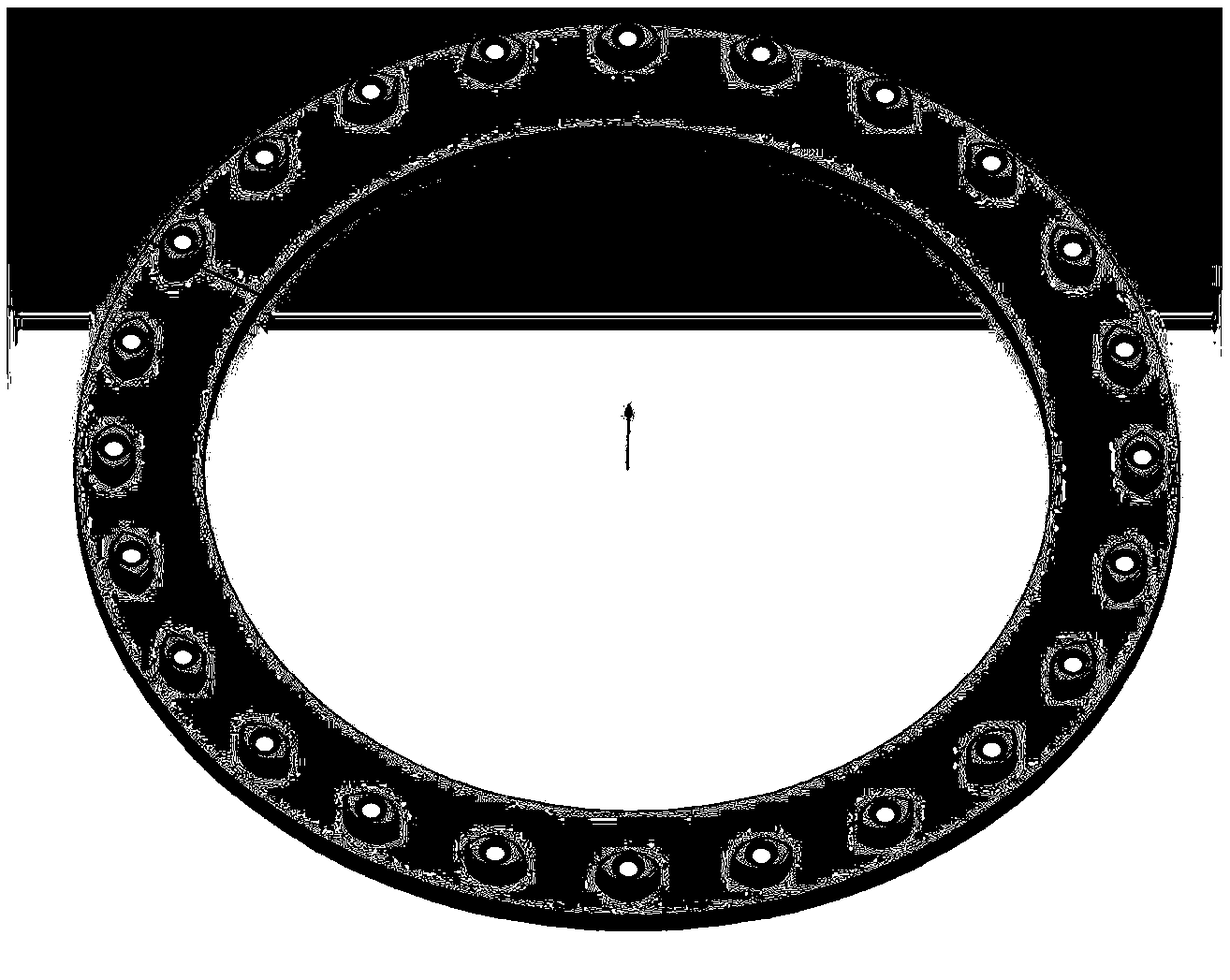
An aero-engine, high-speed rotation technology, applied in the field of aero-engines, can solve the problems of air flow and solid temperature rise, wind resistance temperature rise, material strength performance deterioration, etc., to slow down the air flow and solid temperature rise, reduce wind resistance temperature liters, the effect of increasing the service life

Active Publication Date: 2019-02-01
AECC SHENYANG ENGINE RES INST
View PDF5 Cites 0 Cited by
  • Summary
  • Abstract
  • Description
  • Claims
  • Application Information

AI Technical Summary

Problems solved by technology

[0002] With the increase of the rotational speed of the aeroengine rotating disk, the temperature rise caused by the wind resistance of the bolts on the rotating disk, especially at the high-radius position, is getting higher and higher, which makes the airflow and solid temperature in the vicinity of the bolts and the downstream rotor disk cavity area increase, and even It will deteriorate the strength performance of the material, which is not conducive to its long-term life
In the prior art, the bolts used on the rotating disk of the aero-engine are generally standard parts without any streamline design, and the bolts are directly exposed to the airflow in the disk cavity, which leads to a very large flow resistance and a very high temperature rise due to wind resistance

Method used


Image

  • Aero-engine high-speed rotating disk bolt drag reduction design method and rotating disk
  • Aero-engine high-speed rotating disk bolt drag reduction design method and rotating disk
  • Aero-engine high-speed rotating disk bolt drag reduction design method and rotating disk

Examples


Embodiment Construction

[0021] In order to make the objectives, technical solutions and advantages of the present invention clearer, the technical solutions in the embodiments of the present invention will be described in more detail below in conjunction with the drawings in the embodiments of the present invention. In the drawings, the same or similar reference numerals denote the same or similar elements or elements having the same or similar functions throughout. The described embodiments are some, but not all, embodiments of the invention. The embodiments described below by referring to the figures are exemplary and are intended to explain the present invention and should not be construed as limiting the present invention. Based on the embodiments of the present invention, all other embodiments obtained by persons of ordinary skill in the art without creative efforts fall within the protection scope of the present invention. Embodiments of the present invention will be described in detail below ...


PUM


Abstract

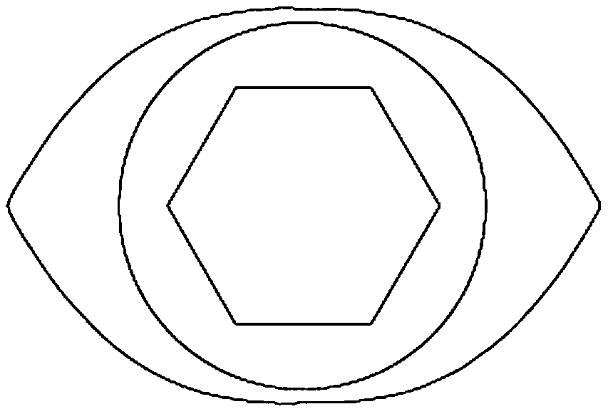
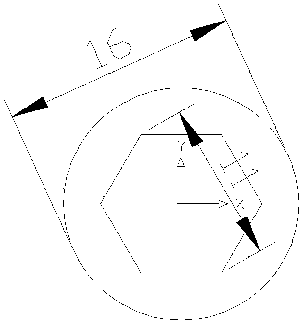
The invention discloses an aero-engine high-speed rotating disk bolt drag reduction optimization method. The optimization method comprises the following steps: determining the diameter and position ofa reference circle and a circle where a leading edge or a trailing edge arc is located; drawing a plurality of outer contours of the bolt cover according to a circle where the leading edge or the trailing edge arc is located; obtaining resistance coefficients of different outer contours, and obtaining resistance coefficients of the bolts, and obtaining optimization direction of outer contour design of the bolt cover by comparing resistance coefficients of different outer contours with resistance coefficients of the bolts. The bolt cover obtained by the bolt drag reduction optimization methodof the high-speed rotating disk of the aero engine provided by the embodiment of the invention can solve the problem of bolt drag reduction under high-speed rotation. The invention can reduce the flowresistance and the temperature rise of the wind resistance, thereby effectively slowing down the rise of the air flow and the solid temperature in the rotor disk cavity area near the bolt and downstream, and prolonging the service life of the rotating disk.

Description

technical field [0001] The invention relates to the technical field of aero-engines, and in particular relates to a design method for drag reduction of high-speed rotating disk bolts of an aero-engine. Background technique [0002] As the rotational speed of the aeroengine rotating disk increases, the temperature rise caused by the wind resistance of the bolts on the rotating disk, especially at the high-radius position, becomes higher and higher, which makes the airflow and solid temperature in the vicinity of the bolts and in the downstream rotor disk cavity area increase, and even It will deteriorate the strength performance of the material, which is not conducive to its lasting life. In the prior art, the bolts used on the rotating disk of the aero-engine are generally standard parts without any streamline design, and the bolts are directly exposed to the airflow in the disk cavity, which leads to a very large flow resistance and a very high temperature rise due to wind ...

Claims


Application Information

Patent Timeline
IPC IPC(8): G06F17/50
CPCG06F2111/06G06F30/17G06F30/20Y02T90/00
Inventor 田申林志辉马增祥李毅
Owner AECC SHENYANG ENGINE RES INST
Learn More