Spray dyeing machine with uniform dyeing

A spray dyeing machine and uniform technology, applied in the field of spray dyeing machines, can solve the problems of large amount of dyeing liquid used and increased processing costs, etc., and achieve the effects of good applicability, saving driving force, and improving utilization rate

Active Publication Date: 2019-02-01
SHAOXING UNIVERSITY
View PDF8 Cites 4 Cited by
  • Summary
  • Abstract
  • Description
  • Claims
  • Application Information

AI Technical Summary

Problems solved by technology

[0004] Although the above-mentioned dyeing machine can improve the dyeing efficiency, because the fabric is immersed in the dye solution, a large amount of dye solution will be attached to the fabric, resulting in a large amount of dye solution used, which increases the processing cost.

Method used


Image

  • Spray dyeing machine with uniform dyeing
  • Spray dyeing machine with uniform dyeing
  • Spray dyeing machine with uniform dyeing

Examples


Embodiment 1

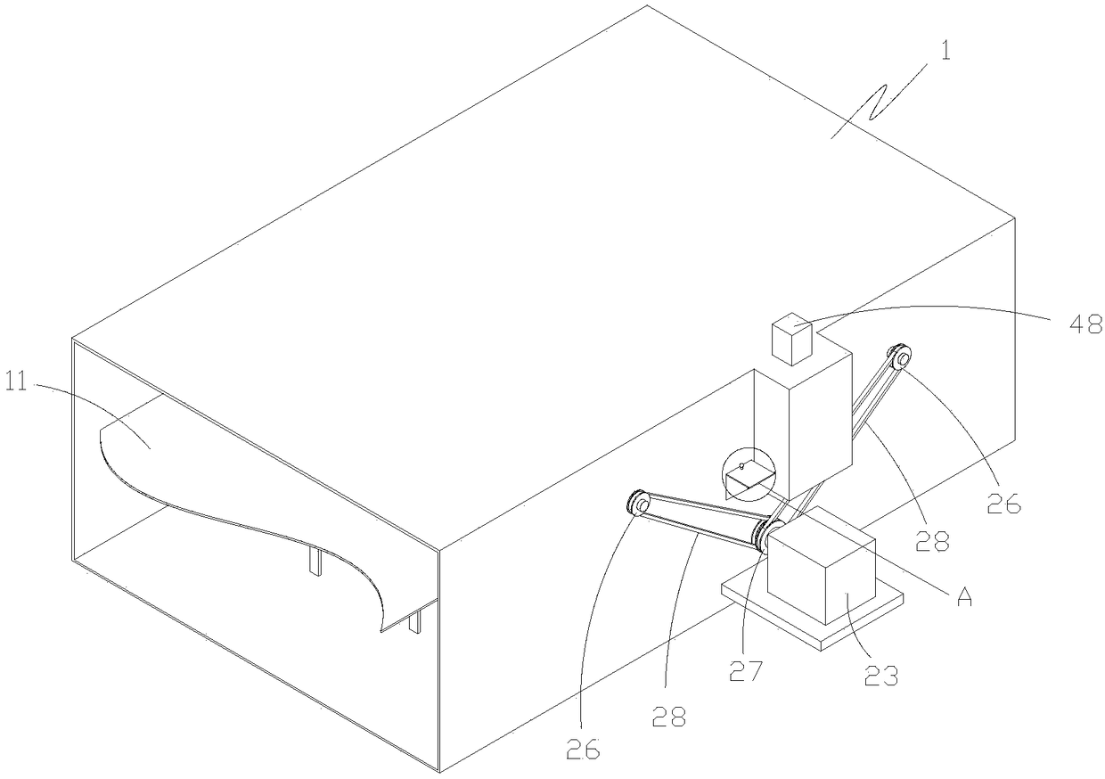
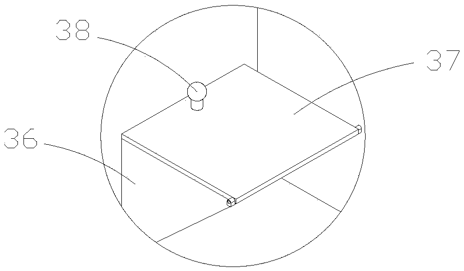
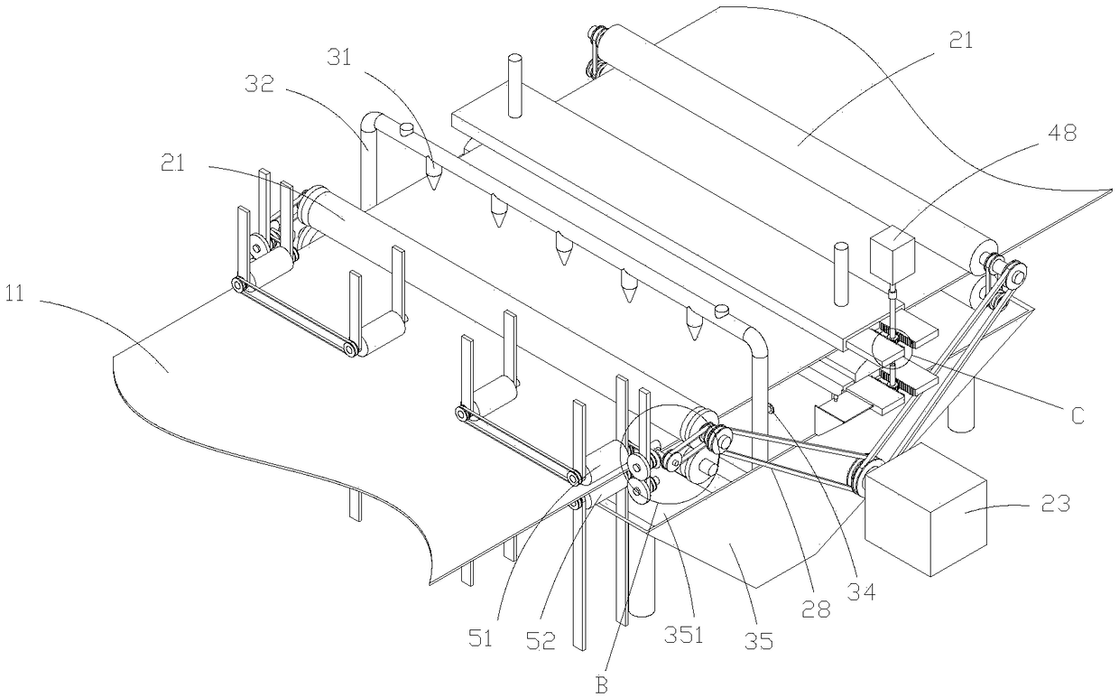
[0030] Such as Figure 1-8 As shown, a spray dyeing machine with uniform dyeing includes a frame 1, a cloth 11, a driving device, a spraying device, a smearing device and a leveling device; wherein the driving device includes a roller shaft group, a first driving member 23 and a roller shaft transmission structure ; This first driving member is the motor that buys on the market, is referred to as No. 1 motor hereinafter, and this is prior art, so do not go into details here; No. 1 motor is installed on the frame 1, and welded on the frame 1 One installation platform, the No. 1 motor is connected with the installation platform by bolts; in this embodiment, two groups of roller shaft groups are installed in total, located on the left side of the spray device and the right side of the smear device, which play the role of conveying the cloth; specifically, the roller shaft The set includes an upper roller shaft 21, a lower roller shaft 22, an upper gear 24 and a lower gear 25; bot...

Embodiment 2

[0042] Such as Figure 9-15 As shown, the difference between this embodiment and Embodiment 1 is that the spraying device is optimized, specifically, the spraying device includes an upper spraying structure, a lower spraying structure, a fourth driving member 78 and a fifth driving member 79, and the upper and lower spraying structures The structure is the same, the upper spraying structure is located above the cloth, and the lower spraying structure is located below the cloth, which are respectively used to spray dyes on the front and back sides of the cloth; the upper spraying structure includes spraying parts 71, recovery parts 72 and feeding components; The material assembly includes a propeller 73, a connecting portion 74 and a feed pipe 75; the connecting portion is bolted to a supporting portion 76, and the two ends of the spraying piece are respectively connected to the two connecting portion bearings, and one end is connected to the fourth connecting portion through a ...


PUM


Abstract

The invention discloses a spray dyeing machine with uniform dyeing. The machine comprises a frame, a raw material roller capable of moving back and forth, a receiving roller capable of moving back andforth, a driving device for driving the movement of the fabric, a spraying device for spraying dyeing liquid and an application device which cooperates with the spraying device; the driving device includes a plurality of roller shaft sets which cooperate with the fabric, a first drive member in driving cooperation with the roller shaft sets and a roller shaft driven structure for achieving the drive cooperation with the first drive member and the roller shaft sets; the spraying device includes a plurality of sprayers uniformly disposed on both sides of the fabric, a spray tube in communication with the sprayers and a feeding member disposed on the spray tube; the machine is provided with the sprayers on both sides of the fabric to uniformly spray the dyeing liquid on the fabric, so that the dyeing is uniform, the consumption of the dyeing liquid is greatly reduced, the energy saving and emission reduction are achieved, and the production cost is reduced; double-sided processing also ensures the processing efficiency.

Description

technical field [0001] The invention belongs to the technical field of printing and dyeing, in particular to a jet dyeing machine for uniform dyeing. Background technique [0002] The textile industry has a history of thousands of years in our country. From the beginning of sericulture and silk reeling in ancient times to the development of the modern textile industry, my country's textile industry has made great progress. In the process of modernization of the textile industry, textile machinery has played an important role. Due to the extensive use of textile machinery, people's hands have been liberated and production efficiency has been improved. Among them, the dyeing machine has also been rapidly improved. [0003] A high-efficiency dyeing machine disclosed in Chinese patent CN106120211B includes a box body, a side of one end of the box body is provided with a feed port, and a roller shaft device is movable inside the box body, and the roller shaft device includes a fir...

Claims


Application Information

Patent Timeline
Patent Type & Authority Applications(China)
IPC IPC(8): D06B1/02D06B23/20D06B23/00
CPCD06B1/02D06B23/00D06B23/20
Inventor 王秀庆张新华何绍木陈坤
Owner SHAOXING UNIVERSITY
Why Eureka
Try Eureka