Eureka AIR delivers breakthrough ideas for toughest innovation challenges, trusted by R&D personnel around the world.

Dustproof electric drill

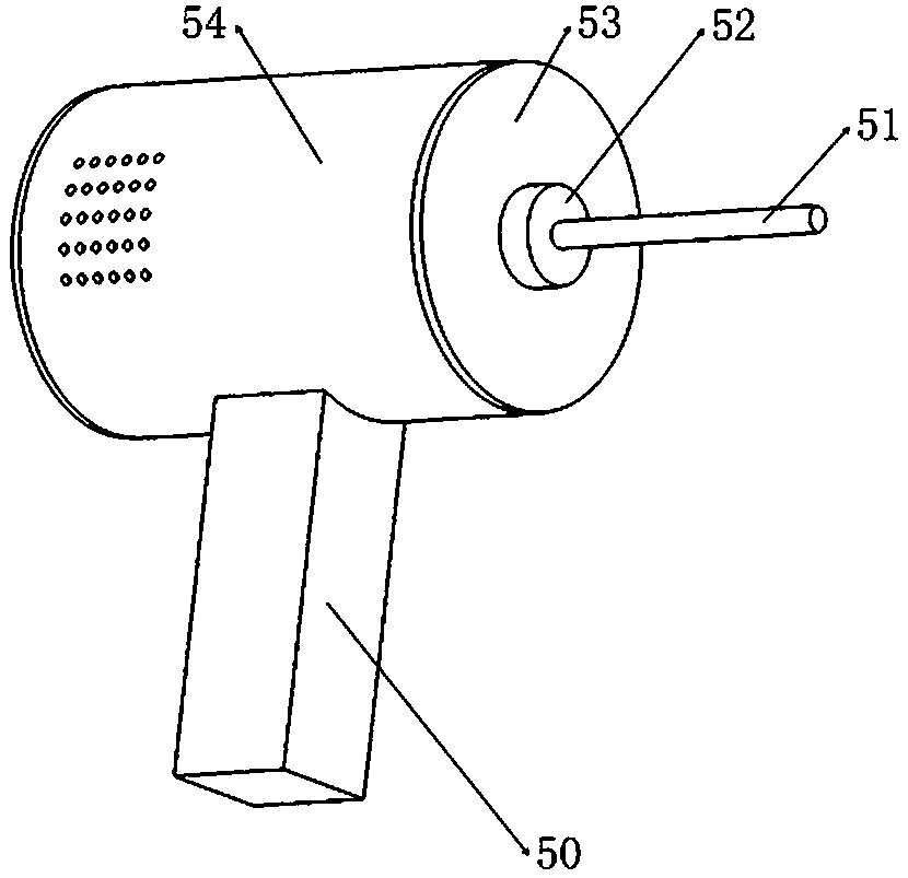
A dust-proof, electric drill technology, used in portable drilling rigs, drilling/drilling equipment, components of boring machines/drilling machines, etc., can solve the problems of heat dissipation and retention of electric drills, and achieve the effect of avoiding mechanical wear

Inactive Publication Date: 2019-02-01
昕致潮贸易(深圳)有限公司
View PDF0 Cites 4 Cited by
  • Summary
  • Abstract
  • Description
  • Claims
  • Application Information

AI Technical Summary

Problems solved by technology

In order to prevent the internal operation failure of the electric drill due to overheating inside the electric drill, the traditional electric drill generally has an exhaust heat dissipation device inside, and the electric drill shell also has ventilation holes for heat dissipation; however, the electric drill is not used and placed in a dusty place In the decoration environment, a large amount of dust is easy to stay inside the electric drill through the ventilation holes, and the accumulation of more dust inside the electric drill will affect the heat dissipation of the electric drill

Method used


Image

  • Dustproof electric drill
  • Dustproof electric drill
  • Dustproof electric drill

Examples


specific Embodiment approach

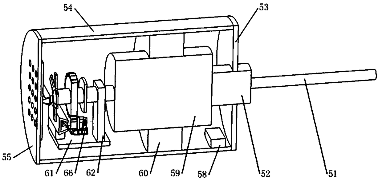
[0042] Specific embodiments: when the electric drill of the present invention needs to be stopped, the control switch on the handle 50 is turned off, and the control module 58 receives the signal of closing the reduction motor 59. At this time, the control module 58 controls the reduction motor 59 to reverse several times, and then completely Stop reduction motor 59. When the reduction motor 59 reverses, the drive shaft 1 drives the friction wheel 2 and the drive gear 3 to reverse, and the drive gear 3 and the friction wheel 2 are set to rotate counterclockwise. Such as Figure 12 As shown, when the rotation direction of the friction wheel 2 is counterclockwise, driven by the friction of the friction wheel 2, the arc-shaped friction plate 35 will slide on the outer circular surface of the friction wheel 2 along the counterclockwise rotation direction of the friction wheel 2 The arc-shaped friction plate 35 will make the sliding plate 29 swing around the center of the pin 37, ...


PUM


Abstract

The invention belongs to the technical field of electric drills, and particularly relates to a dustproof electric drill. The dustproof electric drill comprises a driving shaft, a friction wheel, a driving gear, a second dustproof mechanism, a first dustproof mechanism and an actuating mechanism, first matching holes are matched with air exhaust holes, and second matching holes are matched with airinlet holes. The dustproof electric drill is characterized in that when the electric drill is not used, multiple rows of the second matching holes formed in an arc-shaped baffle and multiple rows ofthe air inlet holes formed in a cylinder shell are distributed in a staggered mode, multiple rows of the first matching holes formed in a square baffle and multiple rows of the air exhaust holes formed in a back cover are distributed in a staggered mode, the purpose of preventing dust in outside air from entering the cylinder shell is achieved, and the condition that heat dissipation of the electric drill is not facilitated after a large amount of dust in the outside enters the electric drill is avoided; and when multiple rows of the second matching holes formed in the arc-shaped baffle communicate with multiple rows of the air inlet holes formed in the cylinder shell and multiple rows of the first matching holes formed in the square baffle communicate with multiple rows of the air exhaustholes formed in the back cover, an exhaust fan can normally conduct heat dissipation on the electric drill, and the normal working requirement of the electric drill is met.

Description

technical field [0001] The invention belongs to the technical field of electric drills, in particular to a dust-proof electric drill. Background technique [0002] At present, in the house decoration process, decorators will often use electric drills to drill holes in the body of wall. For the traditional electric drill for decoration, in order to prevent the motor from running frequently during the long-term frequent use of the electric drill, the temperature inside the electric drill will rise rapidly. In order to prevent the internal operation failure of the electric drill due to overheating inside the electric drill, the traditional electric drill generally has an exhaust heat dissipation device inside, and the electric drill shell also has ventilation holes for heat dissipation; however, the electric drill is not used and placed in a dusty place In the decoration environment, a large amount of dust is easy to stay inside the electric drill through the ventilation holes...

Claims


Application Information

Patent Timeline
Patent Type & Authority Applications(China)
IPC IPC(8): B23B45/02B23B47/06B25F5/00
CPCB23B45/02B23B45/003B23Q5/10B25F5/00
Inventor 陈红
Owner 昕致潮贸易(深圳)有限公司
Why Eureka
Eureka Blog
Learn More