


Quick Research
Generate reliable direction feasibility study reports for your R&D in just a few steps.

Technical Q&A
Discover and master advanced knowledge NOW. Basics, ideas, possibilities, all at once.

Find Solutions
As an expert in R&D theories, this can generate solutions to your technical problems instantly.

Evaluate Feasibility
Analyze your overall solution with one click, know your potential R&D risks in advance.

Monitor Landscape
Get weekly tech updates, stay abreast of the latest tech innovations and key insights.
Elastic extending rod unfolding mechanism
A technology of unfolding mechanism and extension rod, which is applied in the field of elastic extension rod deployment mechanism, which can solve the problems of poor deployment performance and driving force, low deployment accuracy and low folding-expansion ratio, so as to improve the rigidity and reliability of deployment, and improve the deployment Accuracy, easy molding effect
- Summary
- Abstract
- Description
- Claims
- Application Information
AI Technical Summary
Problems solved by technology
Method used
Image

Examples
specific Embodiment approach 1
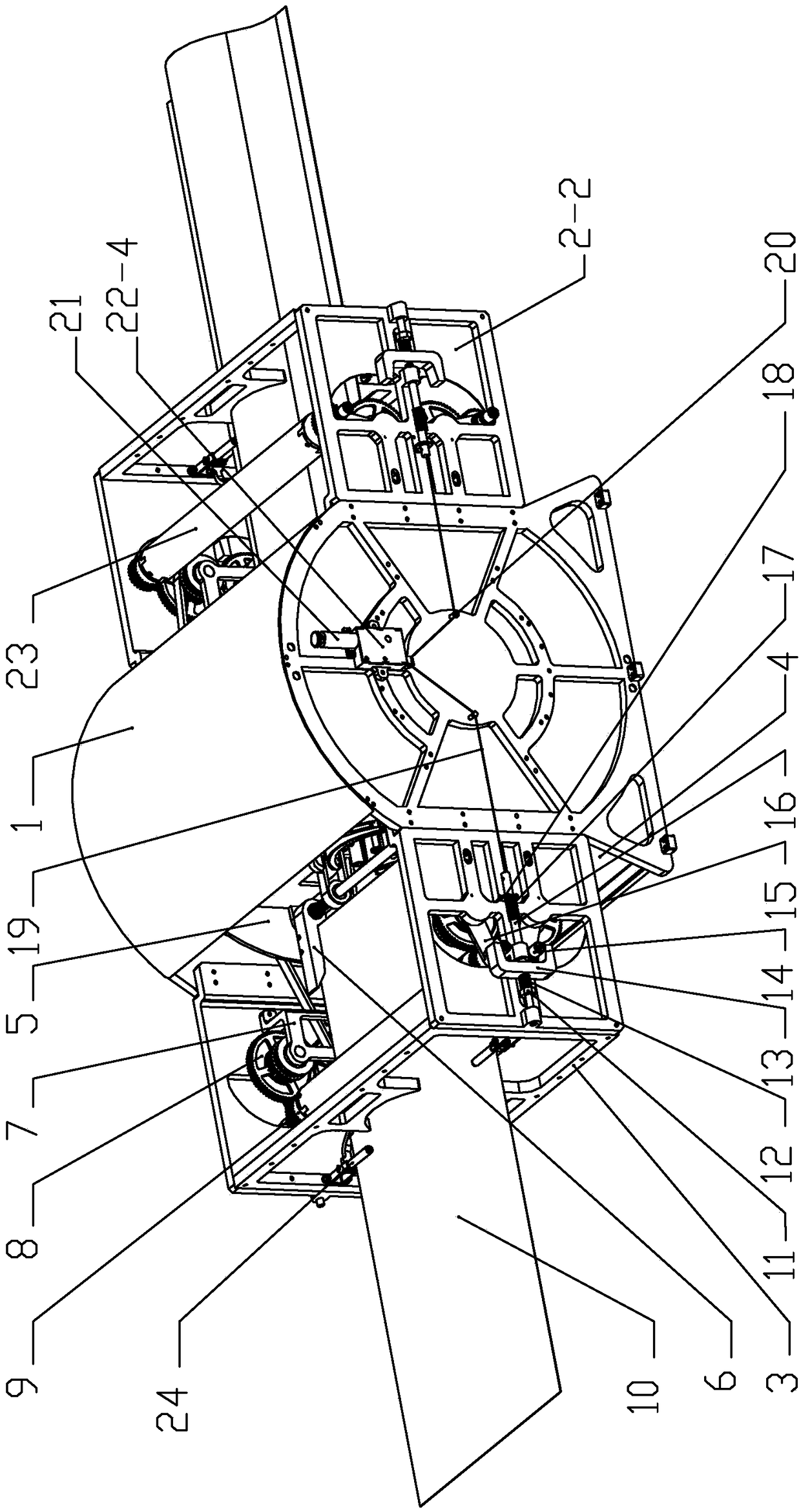
[0029] Specific implementation mode one: combine Figure 1 to Figure 10 Describe this embodiment, an elastic extension rod expansion mechanism of this embodiment includes a support frame, a roller mechanism and a rocker mechanism; the flattened elastic extension rod is wound on the roller of the roller mechanism located in the middle of the support frame, and passed The rotation of the drum controls the expansion and retraction of the elastic rods, and the rocker mechanism located around the drum mechanism converts the rotational motion of the drum mechanism into a translational motion, controlling the flattening or swelling of the elastic rods; it is characterized in that it also includes friction wheels Mechanism, friction wheel power transmission mechanism, sliding lock mechanism, pressure wheel mechanism, guide wheel mechanism and root clamping mechanism, the root clamping mechanism is installed inside the drum of the roller mechanism and fixes the root of the elastic exten...
specific Embodiment approach 2
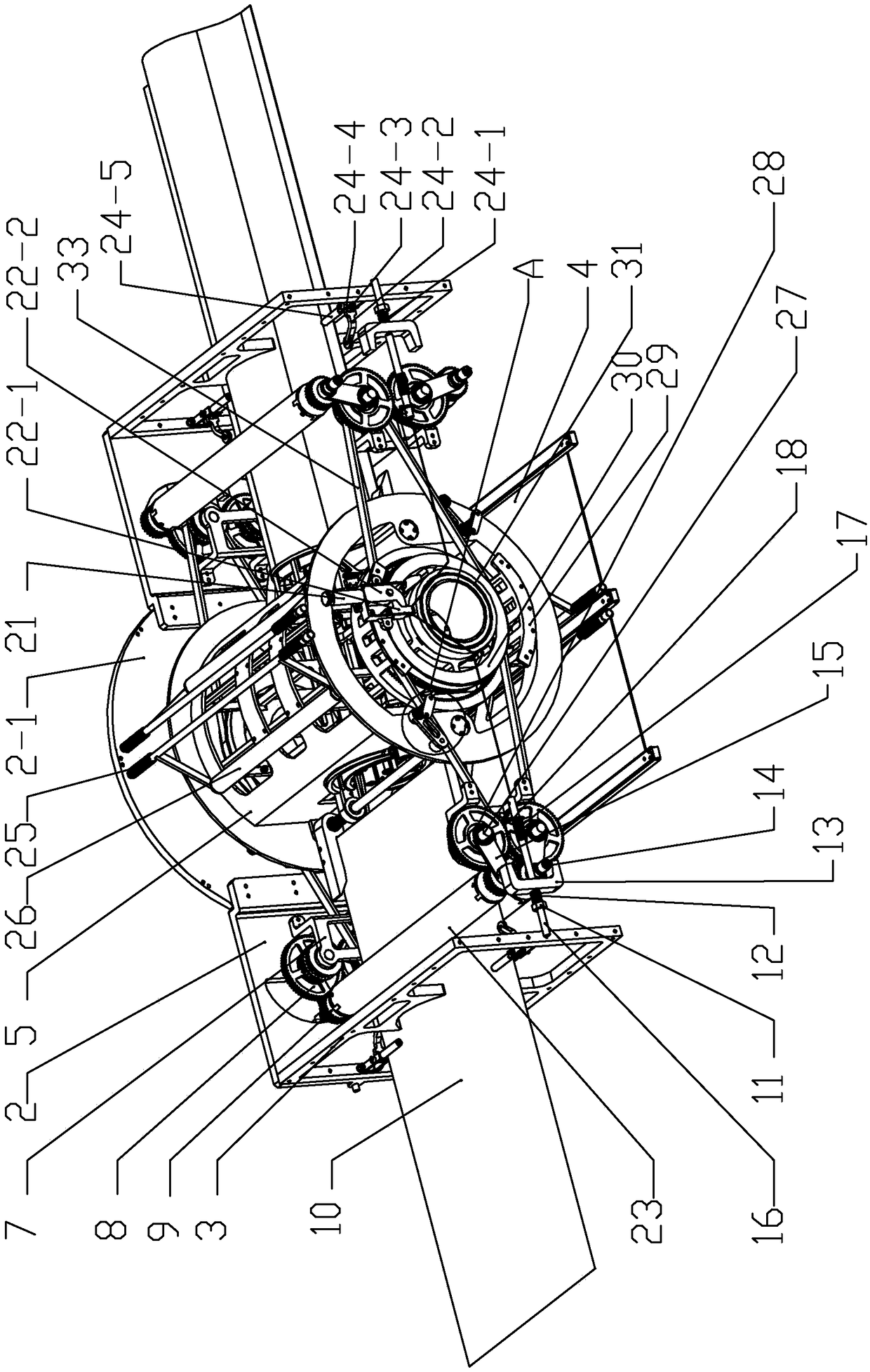
[0031] Specific implementation mode two: combination figure 1 and figure 2 Describe this embodiment, the support frame of this embodiment comprises top cover 1, first side plate 2-1, second side plate 2-2, cage 3 and bottom plate 4, and top cover 1 and bottom plate 4 are respectively installed on the cage 3 on the upper and lower end faces; the second side plate 2-2 has four, the first side plate 2-1 is two circular side plates, and the two circular side plates are installed symmetrically along the length direction of the cage 3, each A second side plate 2-2 is respectively installed on both sides of the circular side plate. Such setting provides support for the installation of other components, and other components and connections are the same as those in Embodiment 1.
specific Embodiment approach 3
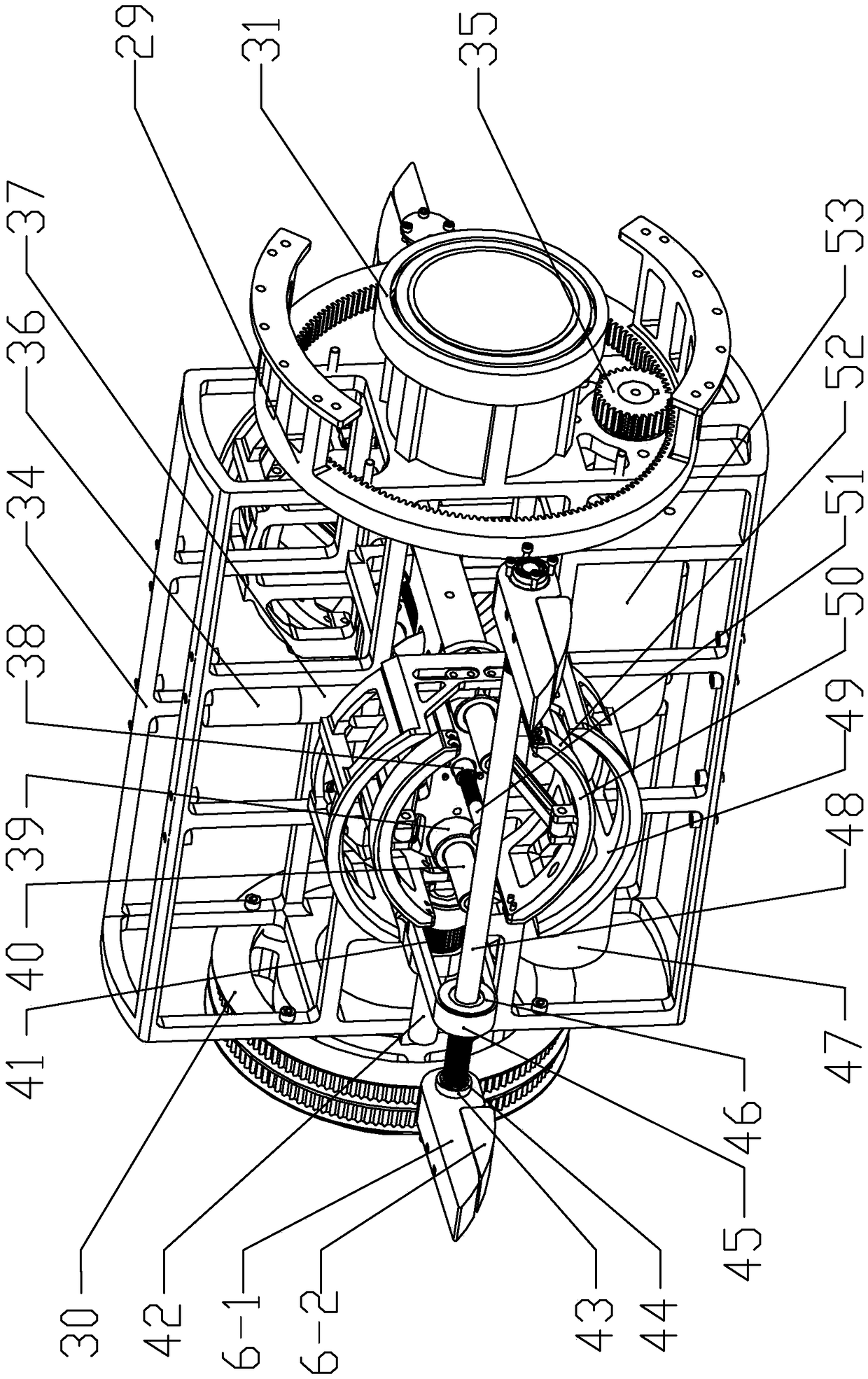
[0032] Specific implementation mode three: combination figure 2 and image 3 Describe this embodiment, the drum mechanism of this embodiment comprises drum 5, main frame 34, ring gear 29, roller bearing 31, pinion 35, first planetary gear reducer 53 and first motor 47, and main frame 34 is installed on In the support frame, the center of the main frame 34 is provided with a central axis, and the two ends of the main frame 34 are respectively equipped with a roller bearing 31 arranged on the first side plate 2-1, and the main frame 34 rotates around the central axis; The cylinder 5 is fixed on the main frame 34, the ring gear 29 is fixedly installed on the first side plate 2-1, the first motor 47 and the first planetary gear reducer 53 are installed in the main frame 34, the output end of the first motor 47 Connected with the first planetary gear reducer 53, the pinion gear 35 is rotatably mounted on the first side plate 2-1, the pinion gear 35 is installed at the output end ...
PUM
 Abstract
Description
Claims
Application Information
 - R&D Engineer
- R&D Manager
- IP Professional
- Industry Leading Data Capabilities
- Powerful AI technology
- Patent DNA Extraction
Browse by: Latest US Patents, China's latest patents, Technical Efficacy Thesaurus, Application Domain, Technology Topic, Popular Technical Reports.
© 2024 PatSnap. All rights reserved.Legal|Privacy policy|Modern Slavery Act Transparency Statement|Sitemap|About US| Contact US: help@patsnap.com