
Magnetic positioning device for exposed steel bar of energy-saving prefabricated member and using method thereof

A technology of magnetic positioning and prefabrication, applied in the direction of manufacturing tools, ceramic molding machines, etc., can solve problems such as easy to be disturbed, inconvenient manual handling, and heavy self-made iron frames, etc., to improve work quality, facilitate manual handling, and high efficiency Effect

Pending Publication Date: 2019-01-29
河南中安征信建筑科技有限公司
View PDF6 Cites 0 Cited by
  • Summary
  • Abstract
  • Description
  • Claims
  • Application Information

AI Technical Summary

Problems solved by technology

The length of the exposed steel bars is not uniform, and the position is deviated, resulting in a large number of PC components that are prone to quality problems during the production stage. Therefore, the size of the exposed steel bars of the PC components needs to be strictly controlled
When the existing PC mobile formwork table and fixed formwork table are binding steel bars, the control of the exposed size of the steel bars is manually adjusted with a steel ruler, and the steel bars can only be bound after the individual long directions are measured and fixed with a self-made iron frame and a steel ruler. There are self-made iron frames. It is too bulky and inconvenient to carry manually. The self-made positioning device is easily disturbed during the production process of the laminated board. The positioning accuracy is not high and the error is large.

Method used


Image

  • Magnetic positioning device for exposed steel bar of energy-saving prefabricated member and using method thereof
  • Magnetic positioning device for exposed steel bar of energy-saving prefabricated member and using method thereof
  • Magnetic positioning device for exposed steel bar of energy-saving prefabricated member and using method thereof

Examples


Embodiment Construction

[0037] The present invention will be described in detail below with reference to the accompanying drawings and examples. It should be noted that, in the case of no conflict, the embodiments in the present application and the features in the embodiments can be combined with each other.

[0038] In the description of the present invention, the terms "longitudinal", "transverse", "upper", "lower", "front", "rear", "left", "right", "vertical", "horizontal", " The orientations or positional relationships indicated by "top", "bottom", etc. are based on the orientations or positional relationships shown in the drawings, and are only for the convenience of describing the present invention and do not require that the present invention must be constructed and operated in a specific orientation, so they cannot be understood as Limitations on the Invention. The terms "connected" and "connected" used in the present invention should be understood in a broad sense, for example, it can be fi...


PUM


Abstract

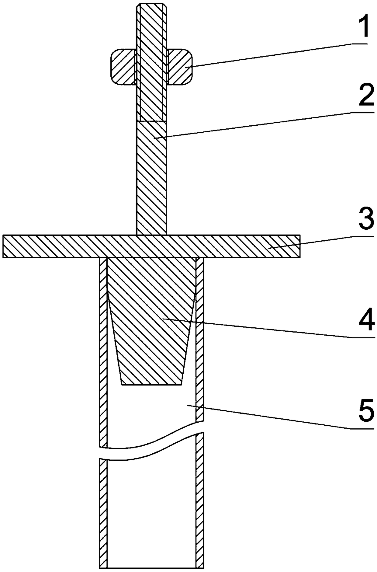
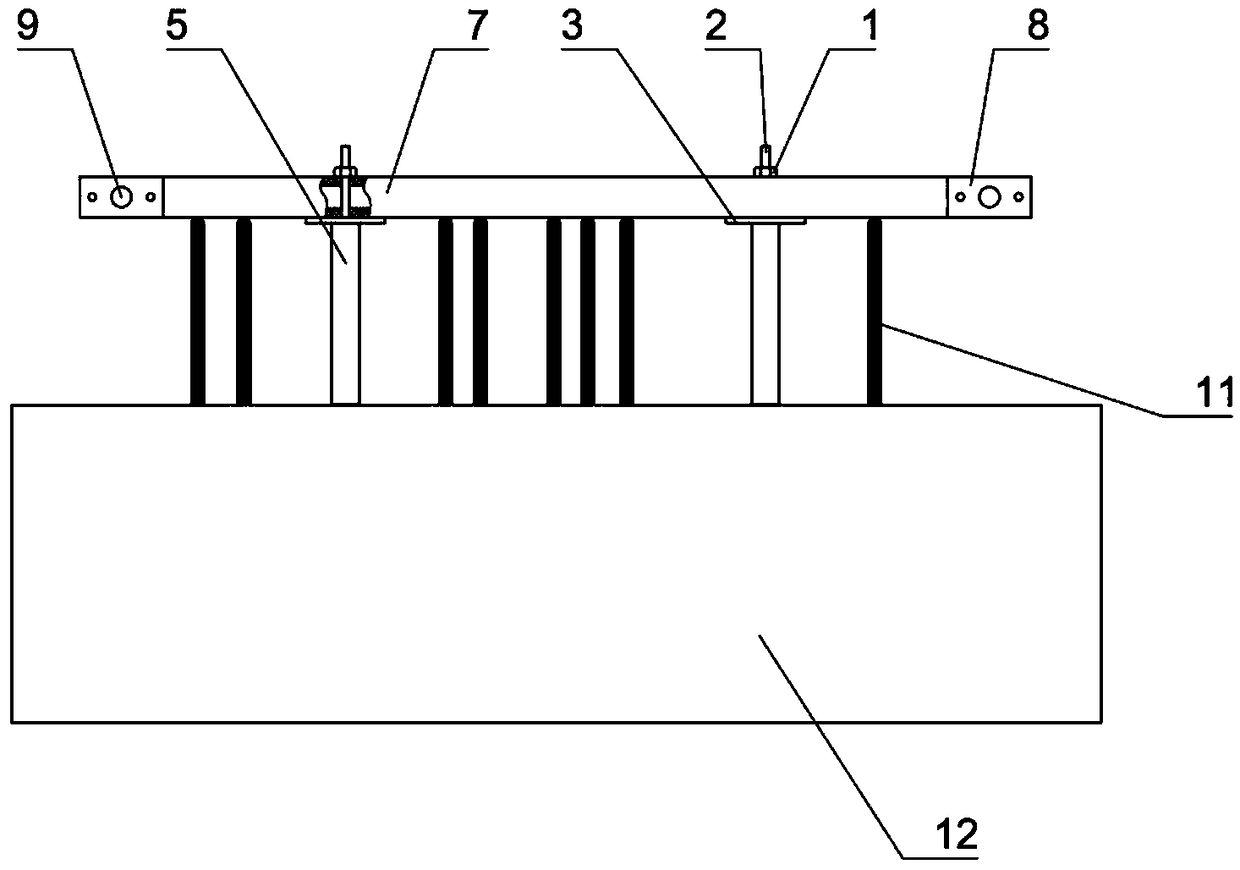
The invention relates to the technical field of construction engineering construction tools, in particular to a magnetic positioning device for an exposed steel bar of an energy-saving prefabricated member and a using method thereof. The magnetic positioning device comprises a quantifying device and a magnetic support, the quantifying device comprises a connecting part, a base plate and a sleeve,the base plate is in a flat plate shape, the connecting part is fixedly arranged on one side face of the base plate, and the sleeve is detachably and vertically connected to the other side face of thebase plate; the magnetic support is in a square column shape and is connected with the quantitative device through the connecting part, and the sleeve and the magnetic support are perpendicular to each other. According to the magnetic positioning device, the position of the positioning device and the length of the exposed steel bar can be freely adjusted according to the size of the component, the overall device is light in weight and convenient to operate manually, in the using process, due to the fact that the positioning device is a whole, errors caused by manual disturbance are avoided, higher efficiency can be achieved when a large amount of products for fixing the exposed size are produced, the fool-type operation is basically realized, and the working quality of construction is effectively improved.

Description

technical field [0001] The invention relates to the technical field of building engineering construction tools, in particular to a magnetic positioning device and a using method for exposed steel bars of energy-saving prefabricated parts. Background technique [0002] Prefabricated components refer to various components manufactured by preforming methods. Unlike on-site manufacturing, preformed components are usually completed in a professional factory and then transported to the site for use. This concept is mainly used in the field of construction. According to the material properties, it can be divided into steel structure prefabricated components, wood structure prefabricated components, concrete prefabricated components, stone prefabricated components, etc. Among them, the concept of concrete prefabricated components is the most widely used. In the field of construction, prefabricated components are usually equated with reinforced concrete prefabricated components or p...

Claims


Application Information

Patent Timeline
Patent Type & Authority Applications(China)
IPC IPC(8): B28B23/02
CPCB28B23/02
Inventor 郝猛金玉斌花金堂杨小明赵元楷田军
Owner 河南中安征信建筑科技有限公司
Learn More