A banknote receiving assembly and a banknote counting machine

A technology of money counting machine and components, which is applied in the direction of counting mechanism/item, instrument, counting object, etc., can solve the problem of the unfavorable space layout of money counting machine with handle, and achieve the effect of space optimization

Active Publication Date: 2019-01-25
SHANGHAI GOOAO ELECTRONIC TECHNOLOGY CORP
View PDF5 Cites 0 Cited by
  • Summary
  • Abstract
  • Description
  • Claims
  • Application Information

AI Technical Summary

Problems solved by technology

[0006] The object of the present invention is to provide a banknote-input component and a banknote counter to solve the problem that the handle and the banknote-input component of the banknote counter in the prior art only work independently, and the design of the handle is unfavorable for the spatial layout of the banknote counter

Method used


Image

  • A banknote receiving assembly and a banknote counting machine
  • A banknote receiving assembly and a banknote counting machine
  • A banknote receiving assembly and a banknote counting machine

Examples


Embodiment Construction

[0031] The technical solutions of the present invention will be further described below in conjunction with the accompanying drawings and through specific implementation methods.

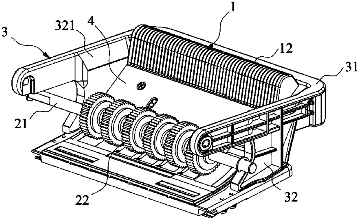
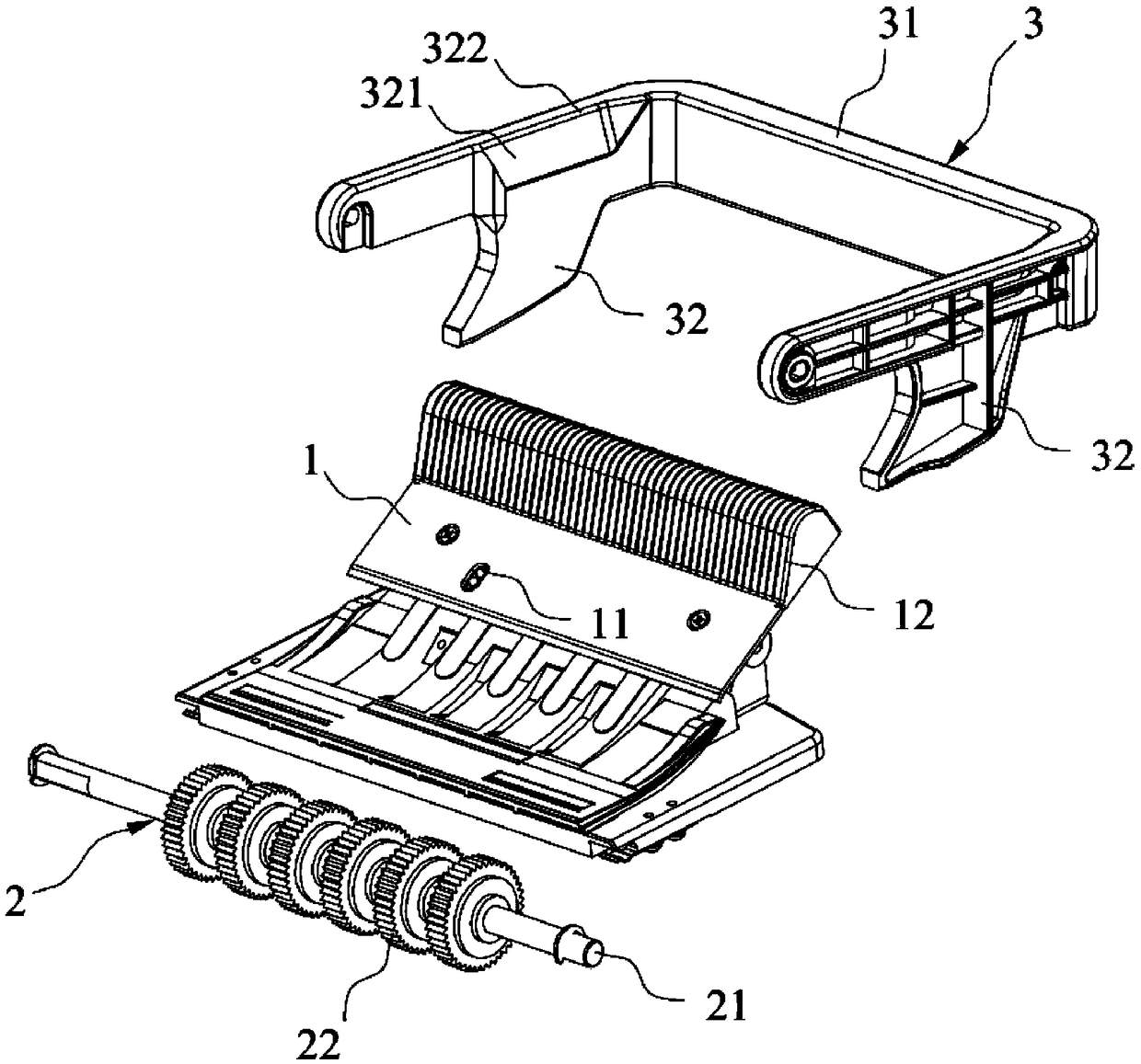
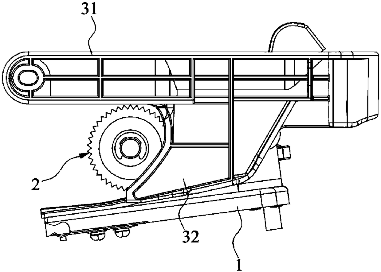
[0032] Such as Figure 1~3 As shown, the present embodiment provides a banknote input assembly, which includes: a banknote input plate 1, a banknote input wheel 2, a handle 3 and a banknote input port 4, and the banknote input plate 1 is installed on the frame of the banknote counter One side of the banknote input plate 1 is provided with a slope, and the banknote input wheel 2 is located in the frame and is tangentially matched with one end of the bottom of the slope. The handle 3 includes a handle body 31 and two shielding parts 32, the two shielding parts 32 are spaced and oppositely arranged on the handle body 31, the handle body 31 is pivotally connected to the frame, the handle body 31 has a first position and a second position, When the handle body 31 was in the first position, the handle bo...


PUM


Abstract

The invention specifically discloses a banknote receiving assembly and a banknote counting machine. The banknote receiving assembly comprises a banknote receiving plate mounted on a rack of the banknote counting machine and provided with an inclined surface on one side; a banknote receiving wheel tangentially matched with the bottom end of the inclined surface; the handle body has a first positionand a second position. When the handle body is located in the first position, the handle body is separated from the banknote receiving plate. When the handle is located in the second position, the two shielding parts abut against the two ends of the banknote receiving plate respectively. A banknote inlet, when the handle is in the second position, the two shielding parts form the left and right ends of the banknote inlet, the front and rear ends of the banknote inlet are formed by the banknote receiving wheel and the banknote receiving plate, and the banknotes put in the banknote inlet can belimited in the left-right direction by the two shielding parts, so that the functions of the handle and the banknote receiving assembly can be mixed, and the space for placing the handle is not required on the banknote counting machine, so that the space of the banknote counting machine is optimized.

Description

technical field [0001] The invention relates to the technical field of banknote counters, in particular to a banknote input component and a banknote counter. Background technique [0002] In daily life, banknote counters are widely used in financial transaction places such as banks, shopping malls, and supermarkets. [0003] The banknote input assembly of the existing banknote counting machine is usually composed of side plates on both sides of the body, a banknote input plate and a banknote input wheel. The banknote input wheel and the banknote input plate are tangentially matched, and the banknote paper is put in from the banknote input port, and under the action of the banknote input wheel, it is sent into the banknote counting machine one by one for counting. [0004] Some of the handles of the existing banknote counters are pivotally connected to the side plates on both sides of the body, and the handles are exposed, which is not only unsightly, but also causes the ban...

Claims


Application Information

Patent Timeline
Patent Type & Authority Applications(China)
IPC IPC(8): G06M7/06
CPCG06M7/06
Inventor 董衍阳梁框荣陈崇军
Owner SHANGHAI GOOAO ELECTRONIC TECHNOLOGY CORP
Why Eureka
Try Eureka