
Camera shooting module and control method for the camera shooting module

A technology of camera module and control method, which is applied in the direction of image communication, TV, color TV parts, etc., and can solve the problems of high cost, complex and heavy camera module structure, etc.

Inactive Publication Date: 2019-01-25
GOERTEK OPTICAL TECH CO LTD
View PDF12 Cites 9 Cited by
  • Summary
  • Abstract
  • Description
  • Claims
  • Application Information

AI Technical Summary

Problems solved by technology

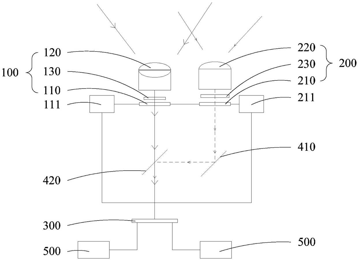
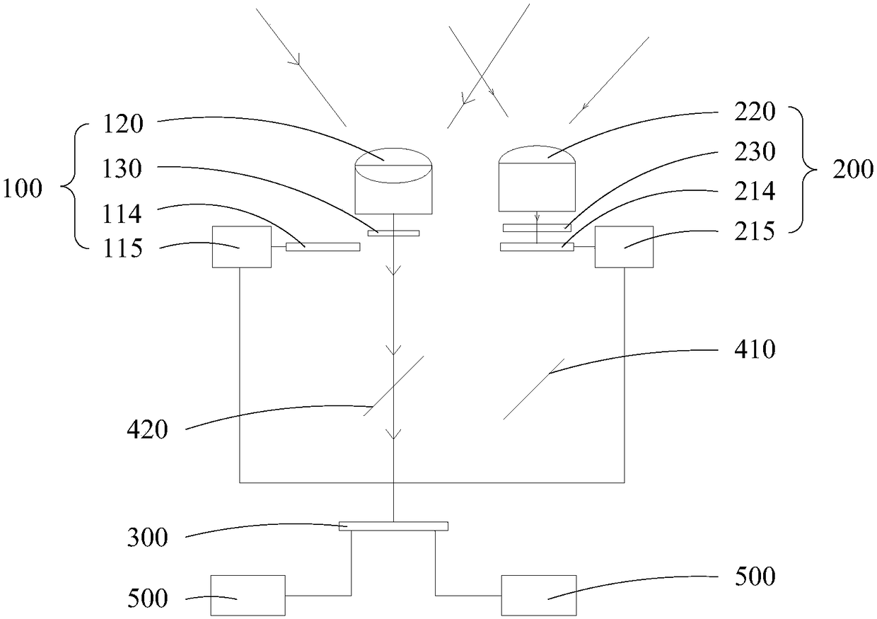
[0003] The main purpose of the present invention is to propose a camera module, aiming to solve the technical problems of complex and heavy structure and high cost in the existing camera module, and to propose a camera module with simple and light structure and low cost

Method used


Image

  • Camera shooting module and control method for the camera shooting module
  • Camera shooting module and control method for the camera shooting module
  • Camera shooting module and control method for the camera shooting module

Examples


Embodiment Construction

[0025] The following will clearly and completely describe the technical solutions in the embodiments of the present invention with reference to the accompanying drawings in the embodiments of the present invention. Obviously, the described embodiments are only part of the embodiments of the present invention, not all of them. Based on the embodiments of the present invention, all other embodiments obtained by persons of ordinary skill in the art without creative efforts fall within the protection scope of the present invention.

[0026] It should be noted that if there is a directional indication (such as up, down, left, right, front, back...) in the embodiment of the present invention, the directional indication is only used to explain the position in a certain posture (as shown in the accompanying drawing). If the specific posture changes, the directional indication will also change accordingly.

[0027] In addition, if there are descriptions involving "first", "second" and ...


PUM


Abstract

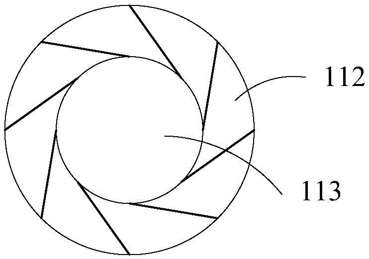
The invention discloses a camera shooting module and a control method for the camera shooting module. The camera shooting module comprises a first imaging assembly, a second imaging assembly and a sensor assembly. The first imaging assembly comprises a first diaphragm. The second imaging assembly includes a second diaphragm. The sensor assembly is located on the exit optical path of the first diaphragm and the sensor assembly is located on the exit optical path of the second diaphragm. When the camera shooting module is operated, the first diaphragm and the second diaphragm are alternately opened such that the sensor assembly alternately receives the first imaging beam generated by the first imaging assembly and the second imaging beam generated by the second imaging assembly. The technical scheme of the invention provides camera shooting module with simple and light structure and low cost.

Description

technical field [0001] The invention relates to the field of imaging technology, in particular to a camera module and a method for controlling the camera module. Background technique [0002] With the development of imaging technology, the functions of camera modules are becoming more and more abundant. In particular, in a camera module, the plane imaging beam that feeds back plane information and the depth imaging beam that feeds back depth information can be processed at the same time, thereby Realize depth vision camera on the basis of realizing traditional plane vision camera. However, in order to deal with imaging light beams of different properties, it is often necessary to set up multiple sets of imaging components, and to set corresponding sensor components corresponding to each imaging component. Alternatively, by setting a group of special imaging components and setting multiple groups of sensor components with different functions for the imaging component, the im...

Claims


Application Information

Patent Timeline
IPC IPC(8): G03B9/06H04N5/225
CPCG03B9/06H04N23/55
Inventor 丁卫涛
Owner GOERTEK OPTICAL TECH CO LTD
Learn More