Hydraulic quick connecting device

A quick-connect, hydraulic technology, applied in the hydraulic field, can solve the problems of radial offset, damage, unstable operation of valve core components, etc., and achieve the effect of ensuring stability and working stability.

Inactive Publication Date: 2019-01-25
常州华睿新能源汽车发展有限公司
View PDF0 Cites 0 Cited by
  • Summary
  • Abstract
  • Description
  • Claims
  • Application Information

AI Technical Summary

Problems solved by technology

When the quick-change joint is connected, the two valve core parts in the female joint and the male joint contact through the flat end surface. Under the action of the pulsating fluid, the valve core part is guided only by the matching gap between the valve core part and the valve seat, causing the valve core part to The work is unstable, and it is easy to produce radial deviation, which will cause the joint to be unstable and damage the rubber sealing ring of the valve core part; when the quick-change joint is disconnected, the working medium will be damaged due to the damage of the rubber sealing ring of the valve core part. leakage of

Method used


Image

  • Hydraulic quick connecting device
  • Hydraulic quick connecting device

Examples


Embodiment Construction

[0012] The present invention will be further described in detail below with reference to the accompanying drawings and embodiments. It should be understood that the specific embodiments described herein are only used to explain the present invention, but not to limit the present invention.

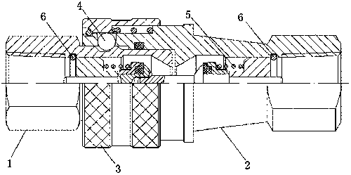
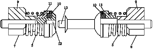
[0013] like Figure 1-Figure 2 As shown, the present invention schematically shows a hydraulic quick connection device.

[0014] The invention discloses a hydraulic quick connection device, such as figure 1 As shown, it includes a joint part and a valve core part, the joint part includes a male joint 1 and a female joint 2, the valve core parts are located in the female joint 2 and the male joint 1 respectively, and the valve core part is fixed to the In the joint, a ferrule 3 is sleeved on the female joint 2, and a steel ball 4 and a spring are arranged under the ferrule 3. When the female joint 2 and the male joint 1 are connected in communication, the steel ball 4 on the female joint...


PUM


Abstract

The invention provides a hydraulic quick connecting device comprising joint parts and valve element parts. The joint parts comprise a male joint and a female joint. The valve element parts comprise avalve seat, a spring, a gland and a valve element part rubber seal ring. The spring is located between the valve seat and the gland, the valve element part rubber seal ring can be respectively in contact seal with the inner conical surfaces of the male joint and the female joint under the elastic force of the spring, a blind hole is formed in one end surface where two valve element parts contact,and a boss short shaft matched with the blind hole is arranged on the other end surface. According to the hydraulic quick connecting device, the blind hole is formed in the male joint valve element part, and the female joint valve element part is provided with the boss short shaft. When the female joint and the male joint are communicated, the boss short shaft is inserted into the blind hole to ensure that the valve element part of a quick change joint is not staggered under the pulsating pressure, and does not generate offset in the radial direction, so that the stability of the valve elementis ensured after the connection, and the working stability of the connected quick change joint is ensured accordingly.

Description

technical field [0001] The invention relates to the field of hydraulic technology, in particular to a hydraulic quick connection device. Background technique [0002] At present, the hydraulic quick-connect device used in the hydraulic pneumatic pipeline system has a flat end face at the top of the valve core component. When the quick-change joint is turned on, the two valve core parts in the female joint and the male joint contact through the flat end faces. Under the action of the pulsating fluid, the valve core parts are guided only by the matching gap between the valve core parts and the valve seat, resulting in the valve core parts. The work is unstable, and it is easy to produce radial deviation, which will cause unstable overcurrent of the joint, which will damage the rubber sealing ring of the valve core part; when the quick-change joint is disconnected, due to the damage of the rubber sealing ring of the valve core part, the working medium will be damaged. of exter...

Claims


Application Information

Patent Timeline
Patent Type & Authority Applications(China)
IPC IPC(8): F16L37/23F16L37/32
CPCF16L37/23F16L37/32
Inventor 何明女
Owner 常州华睿新能源汽车发展有限公司
Why Eureka
Try Eureka