
Electroplating equipment and method of PCB

A technology for PCB circuit boards and electroplating equipment, which is applied in the electrolytic process and electrolytic components, etc., can solve the problems of electroplating quality influence, time-consuming and laborious efficiency, easy to fall off, etc., and achieves the effect of good electroplating effect, reliable fixation and simple operation.

Inactive Publication Date: 2019-01-25
蔡国梁
View PDF1 Cites 3 Cited by
  • Summary
  • Abstract
  • Description
  • Claims
  • Application Information

AI Technical Summary

Problems solved by technology

[0003] In order to solve the above problems, the present invention provides a PCB circuit board electroplating equipment and a PCB circuit board electroplating method, which can solve the problem that the PCB circuit boards with special specifications on the market will be shaken due to unstable clamping during the electroplating process. It will cause uneven plating and affect the effect of subsequent use. At the same time, before the plating of the circuit board, due to human contact or other unavoidable external factors, the surface of the circuit board will be polluted, so that the partially polluted area cannot be electroplated or used after the electroplating is completed. During the process, due to the influence of temperature, etc., it is easy to fall off. Usually, manual cleaning of the surface of the electroplated circuit board is time-consuming and labor-intensive and inefficient. In addition, manual contact during the cleaning process cannot ensure the cleanliness of the surface, which brings great harm to the subsequent electroplating quality. Large impact and other issues; it can realize the functions of fixing PCB circuit boards of different sizes, automatic cleaning and electroplating on the surface of PCB circuit boards, and has the advantages of simple operation, reliable fixing, high cleanliness and good electroplating effect.

Method used


Image

  • Electroplating equipment and method of PCB
  • Electroplating equipment and method of PCB
  • Electroplating equipment and method of PCB

Examples


Embodiment Construction

[0024] In order to make the technical means, creative features, goals and effects achieved by the present invention easy to understand, the present invention will be further described below in conjunction with specific illustrations. It should be noted that, in the case of no conflict, the embodiments in the present application and the features in the embodiments can be combined with each other.

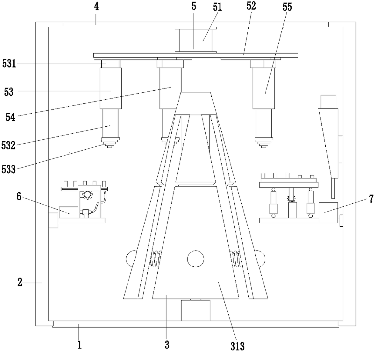
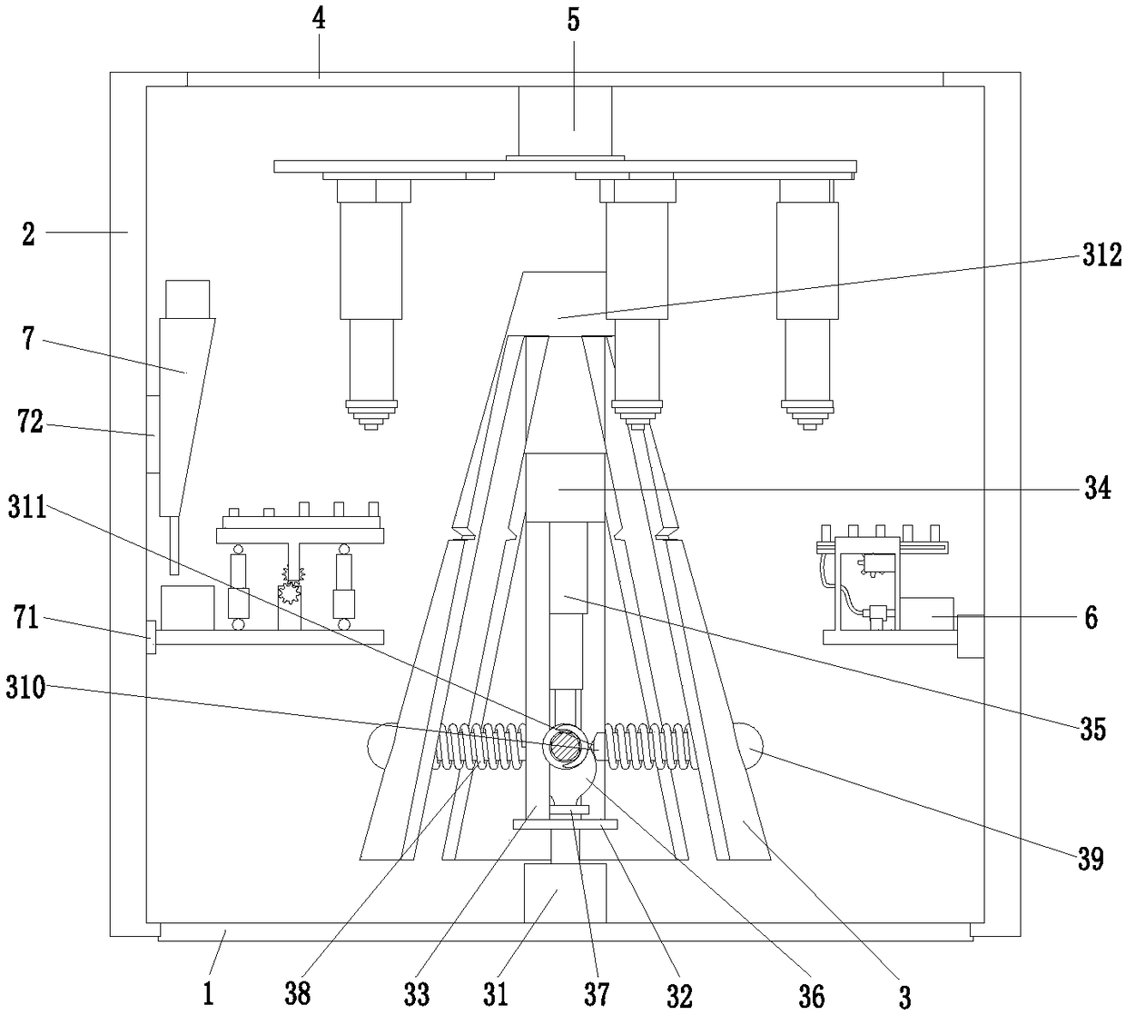
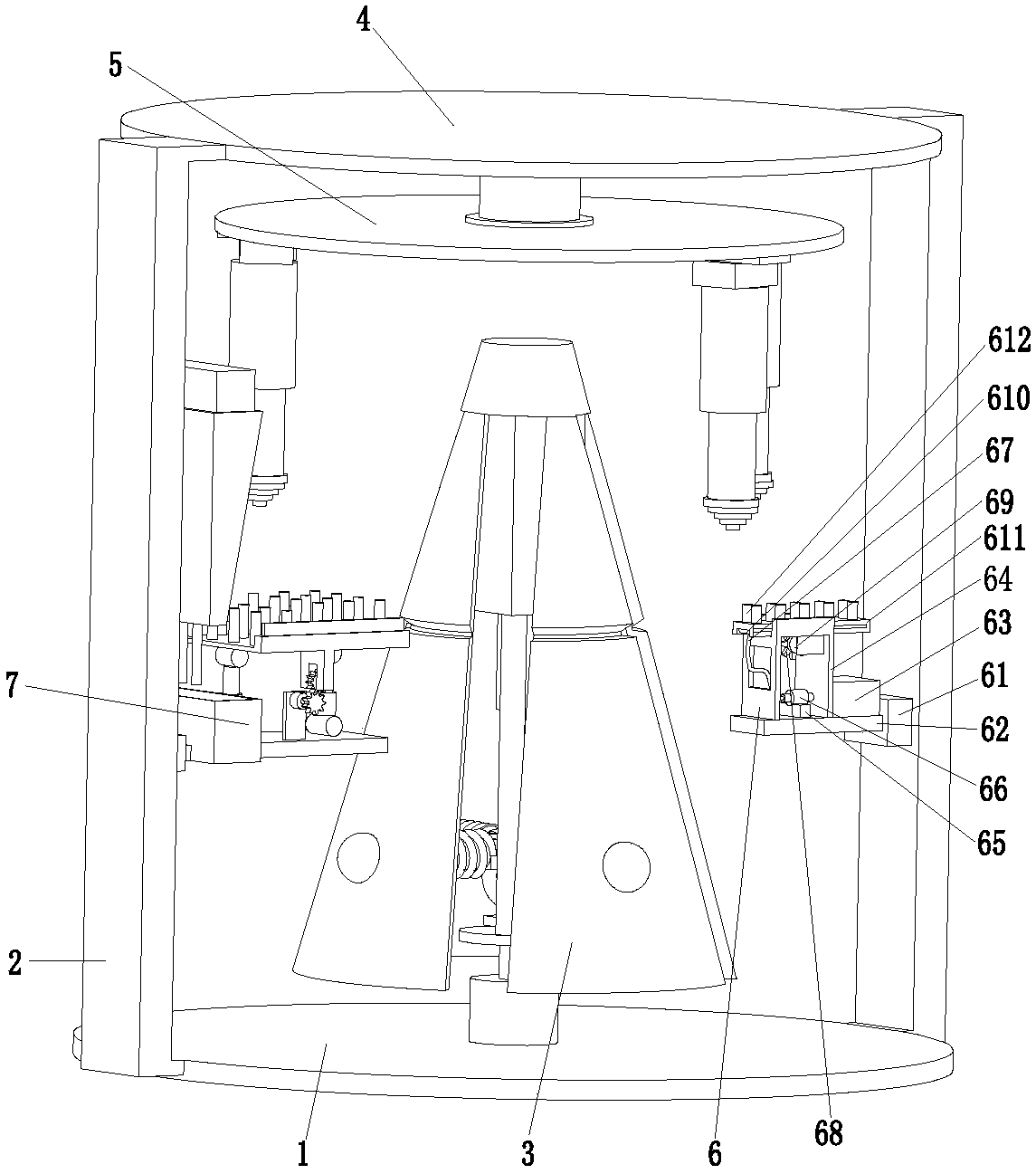
[0025] Such as Figure 1 to Figure 4 As shown, a PCB circuit board electroplating equipment includes a bottom plate 1, a connecting column 2, a fixing mechanism 3, a top plate 4, a limit mechanism 5, an electroplating device 6 and a cleaning device 7, and the middle part of the bottom plate 1 is equipped with a fixing mechanism 3 , the left and right ends of the base plate 1 are symmetrically installed with connecting columns 2, the cleaning device 7 is installed on the inner wall of the connecting column 2 at the left end of the base plate 1 through a sliding fit, and the inner wall...


PUM


Abstract

The invention provides electroplating equipment and an electroplating method of a PCB. The electroplating equipment comprises a bottom plate, connection columns, a fixed mechanism, a top plate, a limiting mechanism, an electroplating device and a washing device. The electroplating equipment and method which are provided by the invention can solve the problems that in the electroplating process ofthe PCB with a special specification in the market, the wobbles due to being clamped unstably, and consequently the PCB is electroplated unevenly, and the subsequent using effect is affected; meanwhile, before electroplating, the surface of the PCB is likely to be contaminated due to artificial contact or other inevitable external factors, therefore, the contaminated local part fails to be electroplated or is liable to fall off in the using process after electroplating due to the influence of temperature and the like; and generally manual work for cleaning treatment of the surface of the PCB is laborious and low in efficiency, and due to manual contact in the cleaning process, the cleanliness of the surface of the PCB cannot be guaranteed, so that the subsequent electroplating quality is much affected.

Description

technical field [0001] The invention relates to the technical field of PCB circuit board processing, in particular to a PCB circuit board electroplating equipment and a PCB circuit board electroplating method. Background technique [0002] PCB circuit boards, also known as printed circuit boards, are providers of electrical connections for electronic components. The main advantage of using circuit boards is that they greatly reduce wiring and assembly errors, and improve automation levels and production labor rates. However, due to the various specifications of PCB circuit boards, there is a lack of targeted circuit board electroplating equipment in the market. During the electroplating process of circuit boards with special shapes, the common electroplating equipment on the market will be unstable due to clamping. The shaking of the circuit board causes uneven plating, which affects the subsequent use effect. At the same time, before the circuit board is electroplated, due ...

Claims


Application Information

Patent Timeline
IPC IPC(8): C25D5/08C25D5/54C25D17/00C25D17/06C25D7/00
CPCC25D5/08C25D5/54C25D7/00C25D17/00C25D17/06
Inventor 蔡国梁
Owner 蔡国梁
Learn More