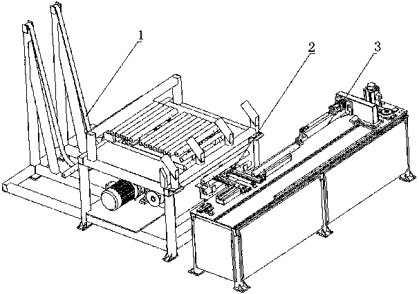
Automatic square tube feeding and servo locating mechanism
A technology of servo positioning and automatic feeding, applied to conveyors, conveyor objects, transportation and packaging, etc., can solve problems such as poor positioning accuracy, achieve the effect of liberating labor, improving positioning accuracy, and realizing automation
Active Publication Date: 2019-01-22
江苏众利达自动化设备有限公司
View PDF6 Cites 9 Cited by
- Summary
- Abstract
- Description
- Claims
- Application Information
AI Technical Summary
Problems solved by technology
For the processing of long workpieces, hydraulic positioning is often used, but the existing servo positioning method, relying on repeated positioning, will produce cumulative errors and poor positioning accuracy
Method used
View moreImage
Smart ImageViewing Examples
Examples
Embodiment Construction
Login to View More PUM
 Abstract
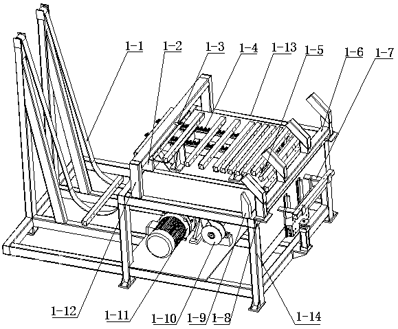
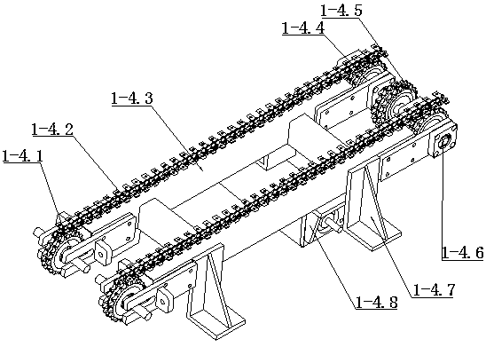
The invention discloses an automatic square tube feeding and servo locating mechanism, and belongs to the technical field of machining automation. The automatic square tube feeding and servo locatingmechanism comprises an automatic square tube feeding mechanism, a servo locating mechanism and a material transferring mechanism. When a hoisting mechanism works, a lifting rope starts to rise, workpieces are driven to ascend, and the workpiece fall onto a chain conveying mechanism through the gravity action. When the workpieces advance one by one along the chain conveying mechanism, after the workpiece advance to a certain position, the workpiece fall along with a guide plate, and are vertically placed under the action of a rear blocking frame. The vertically placed workpieces are pushed by apush air cylinder, and the workpieces are smoothly transferred to a lifting receiving mechanism. After the lifting receiving mechanism receives the workpieces, the workpieces are placed on the material transferring mechanism. The workpieces are transferred to the servo locating mechanism through the material conveying mechanism. The automatic square tube feeding and servo locating mechanism achieves an automatic square tube feeding function and can achieve a servo feeding function on the workpieces, and the locating precision of the workpieces is improved. Automation of square tube machiningis achieved, and labor force is freed up.
Description
technical field The invention relates to the technical field of mechanical processing automation, in particular to an automatic feeding and servo positioning mechanism for square tubes. Background technique With the continuous development of the economy, the call for the liberation of the labor force is getting louder and louder. In the field of mechanical processing, the degree of automation is required to be higher and higher. For the processing of profiles (square tubes, round tubes), the automatic feeding technology for round tubes is relatively mature, while for square tube processing, the automatic feeding technology is obviously lagging behind. For the processing of long workpieces, hydraulic positioning is often used, but the existing servo positioning method relies on repeated positioning, which will generate cumulative errors and poor positioning accuracy. Contents of the invention In order to solve the above technical problems, the present invention provides ...
Claims
Login to View More Application Information
Patent Timeline
 IPC IPC(8): B65G47/82B65G47/24B65G47/28B65G17/46B65G21/20
CPCB65G17/46B65G21/2063B65G47/24B65G47/28B65G47/82B65G2201/0217
Inventor 邵先雨武月超晁岱卫晁岱庆
Owner 江苏众利达自动化设备有限公司
Features
- R&D
- Intellectual Property
- Life Sciences
- Materials
- Tech Scout
- Unparalleled Data Quality
- Higher Quality Content
- 60% Fewer Hallucinations
Learn More Browse by: Latest US Patents, China's latest patents, Technical Efficacy Thesaurus, Application Domain, Technology Topic, Popular Technical Reports.
© 2025 PatSnap. All rights reserved.Legal|Privacy policy|Modern Slavery Act Transparency Statement|Sitemap|About US| Contact US: help@patsnap.com


