
Camera rotation mechanism and control method of a solar infrared sensor camera

A technology of infrared induction and rotation mechanism, which is applied in the direction of use feedback control, etc., can solve the problems of affecting the safety and service life of the camera, the monitoring angle cannot be changed, and the monitoring cost is increased, so as to achieve real-time monitoring of power supply capacity, improve the range, Increase the effect of the mains interface

Active Publication Date: 2019-11-26
ZHONGTIAN BROADBAND TECH +1
View PDF1 Cites 0 Cited by
  • Summary
  • Abstract
  • Description
  • Claims
  • Application Information

AI Technical Summary

Problems solved by technology

[0006] To sum up, the black and white of the infrared sensor camera has the following defects during installation: the camera is fixed, the monitoring angle cannot be changed, and the wind resistance is poor during use, which cannot ensure normal use in bad weather and is prone to falling The situation seriously affects the safety and service life of the camera, and increases the monitoring cost

Method used


Image

  • Camera rotation mechanism and control method of a solar infrared sensor camera
  • Camera rotation mechanism and control method of a solar infrared sensor camera
  • Camera rotation mechanism and control method of a solar infrared sensor camera

Examples


Embodiment 1

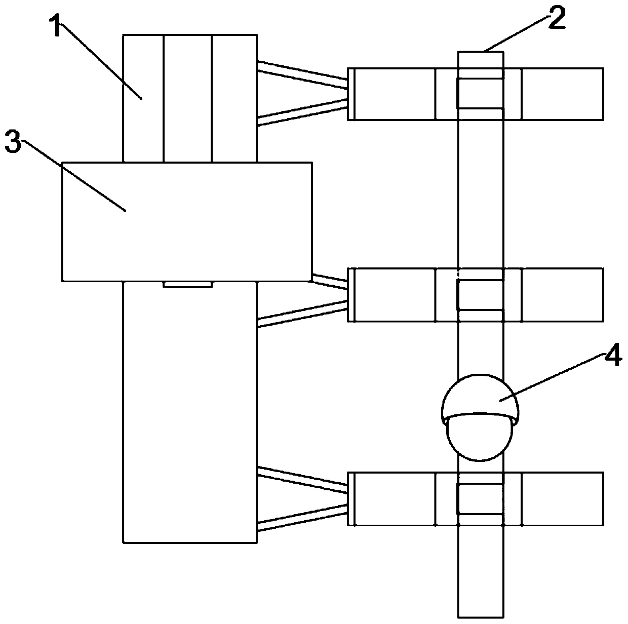
[0043] Such as figure 1As shown, the present invention provides a camera rotation mechanism of a solar infrared sensor camera, a solar panel rotation mechanism of a solar infrared sensor camera, including a receiving arched column 1, and a mounting base 2 connected with the receiving arched column 1, The receiving arch column 1 is provided with a solar panel 3, and the installation base 2 is provided with a camera seat 4, the solar panel 3 in this embodiment is installed on the receiving arch column 1, and can be placed on the To undertake the moving position on the arched column 1, the specific moving method will be described in detail below.

[0044] The mounting base 2 is used to carry the solar panel 3 and the camera, and the mounting base 2 can be set on other objects to realize monitoring, and the camera mounting position 4 is used to install an infrared sensor camera for real-time monitoring.

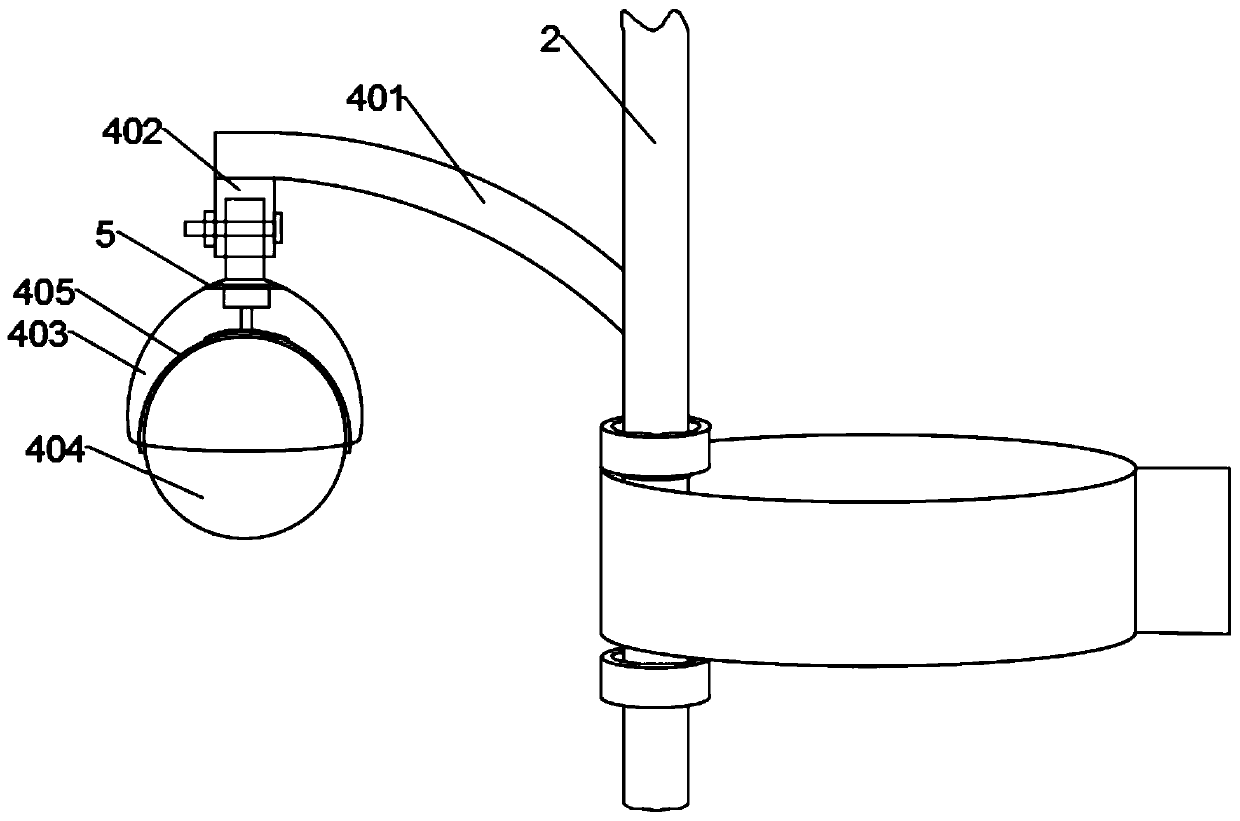
[0045] Such as figure 2 As shown, the camera position 4 includes a curved...

Embodiment 2

[0058] Such as Figure 6 As shown, the present invention also provides a control method of a solar infrared sensor camera according to the solar infrared sensor camera, which specifically includes the following steps:

[0059] Step 1, power supply, connect the solar panel to the battery, and the battery is used to supply power to the infrared sensor camera, camera driving mechanism, battery panel driving components and other electrical devices.

[0060] In this step, the battery is provided with a solar energy interface and a normal power supply interface respectively, and the battery is also connected with a power monitoring module, and the normal power supply interface is also provided with a program-controlled switch connected to the control single-chip microcomputer. When the monitoring module detects that the electric quantity of the accumulator is lower than the set value of low electric quantity, the control single-chip microcomputer controls the program-controlled swit...


PUM


Abstract

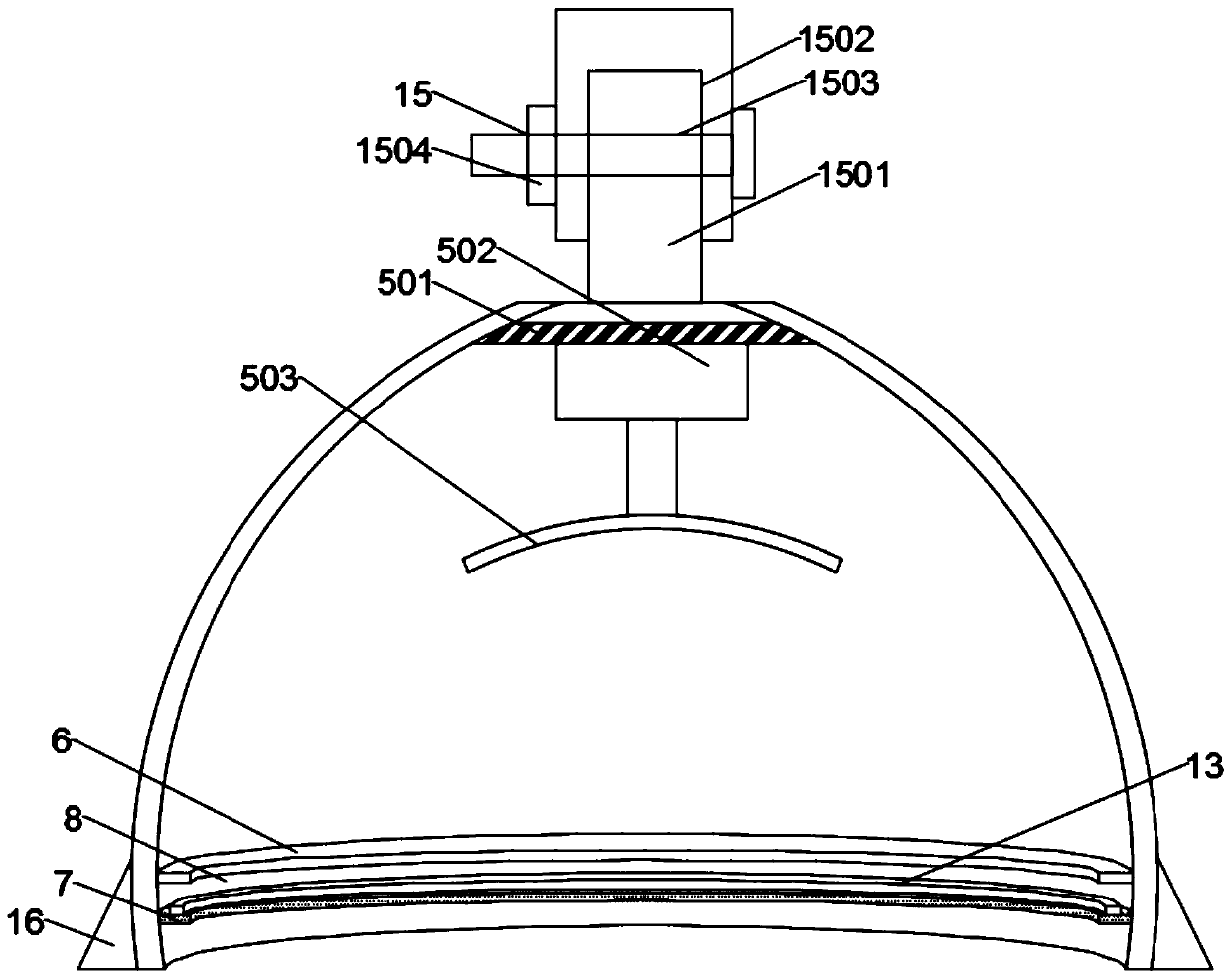
The invention discloses a camera rotation mechanism of a solar infrared induction camera. The camera rotation mechanism comprises a bearing arch post and an installation base, wherein a solar cell panel is arranged on the bearing arch post, a camera load position is arranged on the installation base and comprises a bending stabilization rod and a vertical connection rod, the bending stabilizationrod and the vertical connection rod are fixedly arranged at the installation base, a semi-spherical cover shell is fixedly arranged at a tail end of the vertical connection rod, shooting transparent glass is arranged in the semi-spherical cover shell, a plastic protection shell is pasted with the shooting transparent glass, a camera driving mechanism is further arranged in the semi-spherical covershell, a primary clamping hoop is arranged on an inner wall of an opening of the semi-spherical cover shell, an annular baffle plate is arranged below the primary clamping hoop, an inner sunken clamping groove is formed in the plastic protection shell, and a clamping fixed convex ring is further arranged at the plastic protection shell below the inner sunken clamping groove. With the camera rotation mechanism, multi-direction rotation is achieved, the real-time monitoring range is expanded, installation stability of the camera is achieved, the application safety of the camera is improved, andthe service lifetime of the camera is prolonged.

Description

technical field [0001] The invention relates to the field of infrared induction cameras, in particular to a camera rotation mechanism and a control method of a solar infrared induction camera. Background technique [0002] Infrared cameras have low power supply and use two types of infrared rays: near-infrared rays or short-wave infrared rays with a wavelength of 0.76-1.5 microns, which penetrate deeply into human tissue, about 5-10 mm; far-infrared rays or long-wave infrared rays with a wavelength of 1.5-400 micron, mostly absorbed by the superficial skin, penetrating the tissue to a depth of less than 2 mm, enhancing the ability to capture images at night. So most users need an infrared camera to pursue a strong camera effect. [0003] At present, the traditional monitoring system relies on the operation of power facilities, so in bad weather or other situations that cause power and Internet interruptions, the camera cannot perform normal monitoring functions. Even if the...

Claims


Application Information

Patent Timeline
Patent Type & Authority Patents(China)
IPC IPC(8): G05D3/20
CPCG05D3/20
Inventor 胡浩
Owner ZHONGTIAN BROADBAND TECH
Learn More