Conveyor belt intermittent conveying mechanism

A conveying mechanism and conveyor belt technology, applied in conveyors, transportation and packaging, food science, etc., can solve problems such as affecting the appearance of steamed buns and skewing the top.

Active Publication Date: 2019-01-18
SHANDONG YINYING COOKING MACHINERY
View PDF6 Cites 2 Cited by
  • Summary
  • Abstract
  • Description
  • Claims
  • Application Information

AI Technical Summary

Problems solved by technology

The conveying mechanism of the steamer on the market (such as figure 1 shown): including driving roller 18, pressure roller bracket 19, belt roller 20, conveyor belt 2, cam 15 and transmission rod 23. The cam 15 connected with the driving roller 18 rotates, and the pressure roller bracket 19 and the belt roller 20 are driven up and down by the quick return characteristic of the cam 15 to support the steamed bun dropped by the forming mechanism. After the steamed bun is pinched, the belt supporting mechanism falls, And it is transported forward by the conveyor belt. During the process of pinching the steamed buns, the conveyor belt supports the steamed buns. At the same time, the conveyor belt moves forward at a constant speed, causing the top of the steamed buns to fall on the conveyor belt. package appearance

Method used


Image

  • Conveyor belt intermittent conveying mechanism
  • Conveyor belt intermittent conveying mechanism
  • Conveyor belt intermittent conveying mechanism

Examples


Embodiment Construction

[0014] The present invention will be specifically described below in conjunction with the accompanying drawings and embodiments.

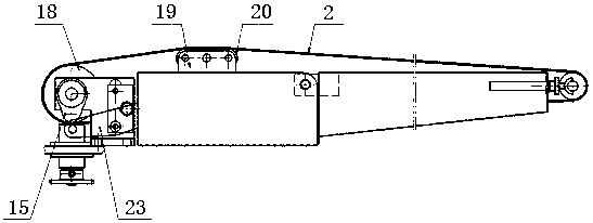
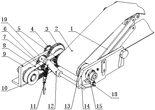
[0015] figure 2 Shown is the structural representation of the present invention.

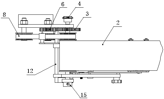
[0016] image 3 Shown is a schematic top view of the structure of the present invention.

[0017] The present invention comprises a supporting belt mechanism 1, a conveyor belt 2, a large gear 3, a bevel gear 4, a synchronous belt driven wheel 5, a pinion 6, a synchronous belt driving wheel 7, a synchronous belt 8, a left bracket 9, a tension spring 11, a pressing Wheel combination 12, conveyor belt roller 13, right support 14, cam 15, fixed shaft 16 and driving shaft 17.

[0018] The two ends of the drive shaft 17 are supported by the left bracket 9 and the right bracket 14, one end of the drive shaft 17 is coaxially fixed with a bevel gear 4 and a large gear 3, the other end is connected with a cam 15 through a key, and the conveyor belt roller 13 is hinged thr...


PUM


Abstract

The invention discloses a conveyor belt intermittent conveying mechanism. The conveyor belt intermittent conveying mechanism includes a support belt mechanism, a conveyor belt, a bull gear, a bevel gear, a synchronous belt driven wheel, a pinion, a synchronous belt driving wheel, a synchronous belt, a left bracket, a tension spring, a pinch roller combination, a conveyor belt roller, a right bracket, a cam, a fixed shaft and a driving shaft, wherein two ends of the driving shaft are supported by the left and right brackets; one end of the driving shaft is coaxially fixed with the bevel gear and the bull gear, and the other end of the driving shaft is connected with the cam through a key; the conveyor belt roller is hinged to the driving shaft through a bearing; the synchronous belt drivenwheel is fixed at one end of the conveyor belt roller; the synchronous belt driving wheel and the pinion are coaxially fixed on the fixed shaft; the synchronous belt driving wheel drives the synchronous belt driven wheel through the synchronous belt to drive the conveyor belt roller to rotate; and two ends of the pinch roller combination are hinged to the left and right brackets respectively, andare pressed on the synchronous belt by the tension spring. The conveyor belt intermittent conveying mechanism changes the movement mode of the conveyor belt, and solves the problem that the top of a steaming package is skewed and the appearance is not beautiful due to the movement of the conveyor belt.

Description

technical field [0001] The invention relates to a conveyer belt intermittent conveying mechanism, in particular to a conveyer belt intermittent conveying mechanism for a steamer, belonging to the technical field of cooking machinery. Background technique [0002] The conveying mechanism of the steamed bun machine is installed under the forming mechanism of the steamed bun machine. After the steamed buns are formed, they fall on the conveyor belt and are transported forward by the conveyor belt. The conveying mechanism of the steamer on the market (such as figure 1 shown): including driving roller 18, pressure roller bracket 19, belt roller 20, conveyor belt 2, cam 15 and transmission rod 23. The cam 15 connected with the driving roller 18 rotates, and the pressure roller bracket 19 and the belt roller 20 are driven up and down by the quick return characteristic of the cam 15 to support the steamed bun dropped by the forming mechanism. After the steamed bun is pinched, the b...

Claims


Application Information

Patent Timeline
Patent Type & Authority Applications(China)
IPC IPC(8): B65G15/60B65G23/24
CPCA23P20/20B65G15/60B65G23/24
Inventor 贾连东焦峰李传光焦念雷李肇磊
Owner SHANDONG YINYING COOKING MACHINERY
Why Eureka
Try Eureka