
Dynamic wireless charging receiving device of electric vehicle

A wireless charging and receiving device technology, applied in the field of electric vehicle dynamic wireless charging receiving devices, can solve the problems of short charging coupling time, reduced vertical spacing charging efficiency, and high charging efficiency, so as to ensure continuity, better charging effect, and maintain The effect of precise coupling

Active Publication Date: 2019-01-18
HEFEI UNIV OF TECH
View PDF9 Cites 1 Cited by
  • Summary
  • Abstract
  • Description
  • Claims
  • Application Information

AI Technical Summary

Problems solved by technology

[0003] The disadvantage of the existing technology is that the speed of the vehicle is fast when the vehicle is running normally, and the vehicle-mounted electromagnetic receiving device moves quickly relative to the road surface electromagnetic transmitting device. When the coils are in the facing state, the charging efficiency reaches the highest. When the vehicle is moving at high speed, it cannot be guaranteed that the centers of the two are always on the same central axis. If the transmitting coil and the receiving coil are offset, the charging efficiency will be greatly reduced; at the same time, due to the existing Due to the limitation of factors, too large vertical distance between the transmitting coil and the receiving coil will also reduce the charging efficiency

Method used


Image

  • Dynamic wireless charging receiving device of electric vehicle
  • Dynamic wireless charging receiving device of electric vehicle
  • Dynamic wireless charging receiving device of electric vehicle

Examples


Embodiment Construction

[0027] See attached picture.

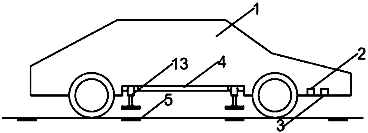
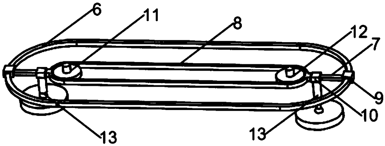
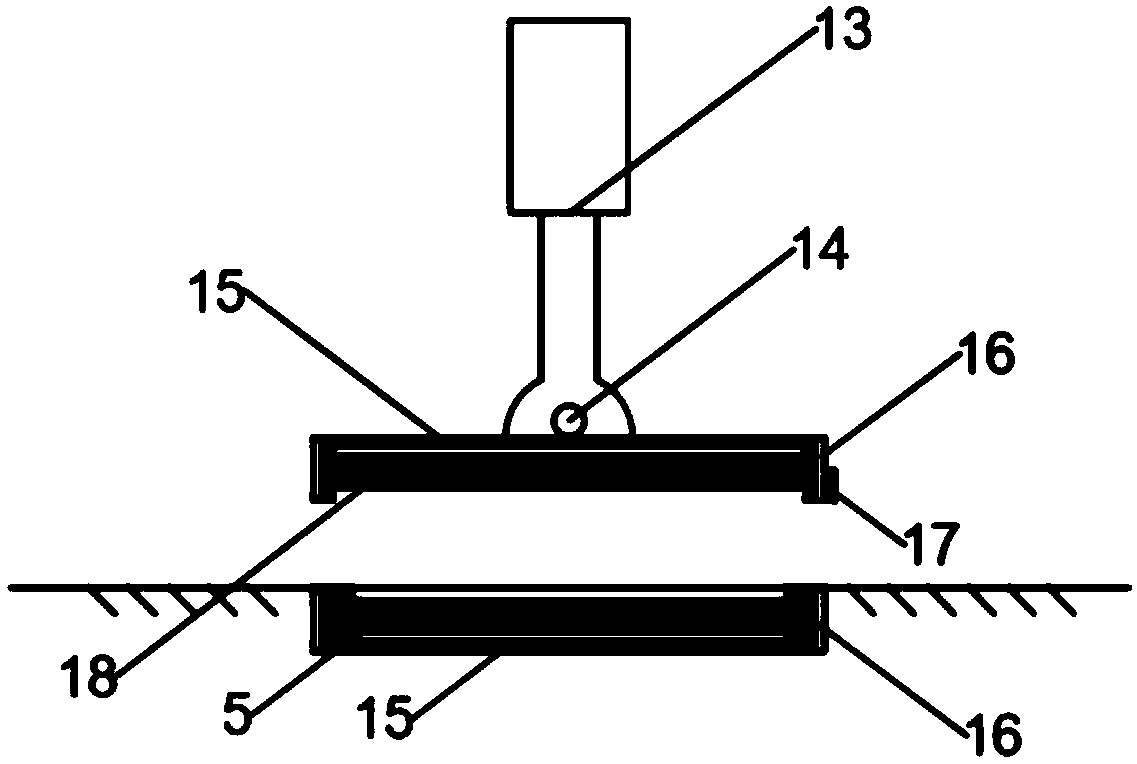
[0028] A dynamic wireless charging receiving device for electric vehicles, including a charging section and a transmitting coil 5 arranged on the road surface of the charging section, including a driving wheel 11 and a driven wheel 12 respectively installed at the front and rear ends of the chassis of the charging vehicle, the driving wheel 11 and the The transmission belt 8 of circulation transmission is set between the driven wheels 12, and the periphery of the transmission belt 8 is provided with a circumferential annular guide rail 6, and a receiving coil adjustment mechanism is arranged between the transmission belt 8 and the circumferential annular guide rail 6; the receiving coil The adjustment mechanism includes a radial guide rail 7 fixed on the annular outer wall of the transmission belt 8. A sliding sleeve 9 is slidably fitted on the radial guide rail 7. A longitudinal expansion rod 13 is installed on the bottom of the sliding sleeve. T...


PUM


Abstract

The invention discloses a dynamic wireless charging receiving device of an electric vehicle. The device comprises a charging road section and a transmitting coil arranged on the road surface of the charging road section, comprising a driving wheel and a driven wheel respectively installed in front of the chassis of the charging vehicle and at the rear two ends thereof, and a drive belt with circulating drive is sleeved between the driving wheel and the driven wheel. Comprises a radial guide rail fixed on an annular outer wall of the transmission belt, a sliding sleeve is slidably fitted on theradial guide rail, and a receiving coil is installed at the bottom of the sliding sleeve through a longitudinal telescopic rod. The invention realizes the continuous coupling of the transmitting coiland the receiving coil through the circulating motion of the two modules on the guide rail, thereby realizing the uninterrupted charging of the electric vehicle and ensuring the continuity of the current. Under the action of radial guide, electric push rod and ball-cage universal joint, the receiving coil can keep precise coupling with the transmitting coil, so as to achieve the purpose of improving the charging efficiency.

Description

Technical field: [0001] The invention relates to the technical field of electric vehicle charging, and mainly relates to a dynamic wireless charging receiving device for electric vehicles. Background technique: [0002] With the aggravation of energy shortage and environmental pollution, electric vehicles as new energy vehicles have received widespread attention, and electric vehicles will definitely become the mainstream travel tool in the near future. As for the charging method of electric vehicles, the traditional station static wired charging is gradually unable to meet people's growing travel needs due to space constraints and charging time issues. The wireless charging technology has the advantages of convenience and safety, and has become a hot research direction in recent years. The most widely used types of wireless charging are electromagnetic induction and magnetic resonance. With the further development of wireless charging technology, in order to be able to ch...

Claims


Application Information

Patent Timeline
Patent Type & Authority Applications(China)
IPC IPC(8): B60L53/12
CPCY02T10/70Y02T10/7072Y02T90/14
Inventor 刘凯王博文凡俊生金灿邓皓孙雨欣彭琦徐先明刘力宁童健航
Owner HEFEI UNIV OF TECH
Learn More