
Terminal Equipment

A technology of terminal equipment and casing, which is applied in the field of terminal equipment and can solve the problems of high cost and complex structure of the camera

Active Publication Date: 2019-01-15
VIVO MOBILE COMM HANGZHOU CO LTD
View PDF8 Cites 27 Cited by
  • Summary
  • Abstract
  • Description
  • Claims
  • Application Information

AI Technical Summary

Problems solved by technology

[0005] The invention discloses a terminal device to solve the problems of high cost and complicated structure in the current terminal device that adopts motor-driven camera expansion and contraction

Method used


Image

  • Terminal Equipment
  • Terminal Equipment
  • Terminal Equipment

Examples


Embodiment Construction

[0020] In order to make the purpose, technical solution and advantages of the present invention clearer, the technical solution of the present invention will be clearly and completely described below in conjunction with specific embodiments of the present invention and corresponding drawings. Apparently, the described embodiments are only some of the embodiments of the present invention, but not all of them. Based on the embodiments of the present invention, all other embodiments obtained by persons of ordinary skill in the art without making creative efforts belong to the protection scope of the present invention.

[0021] The technical solutions disclosed by various embodiments of the present invention will be described in detail below in conjunction with the accompanying drawings.

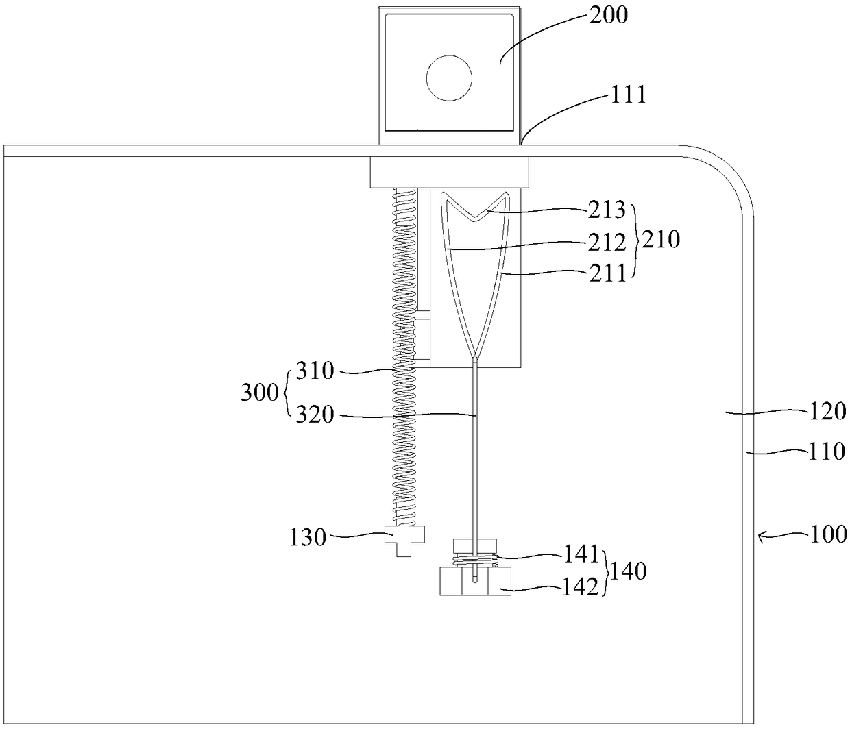
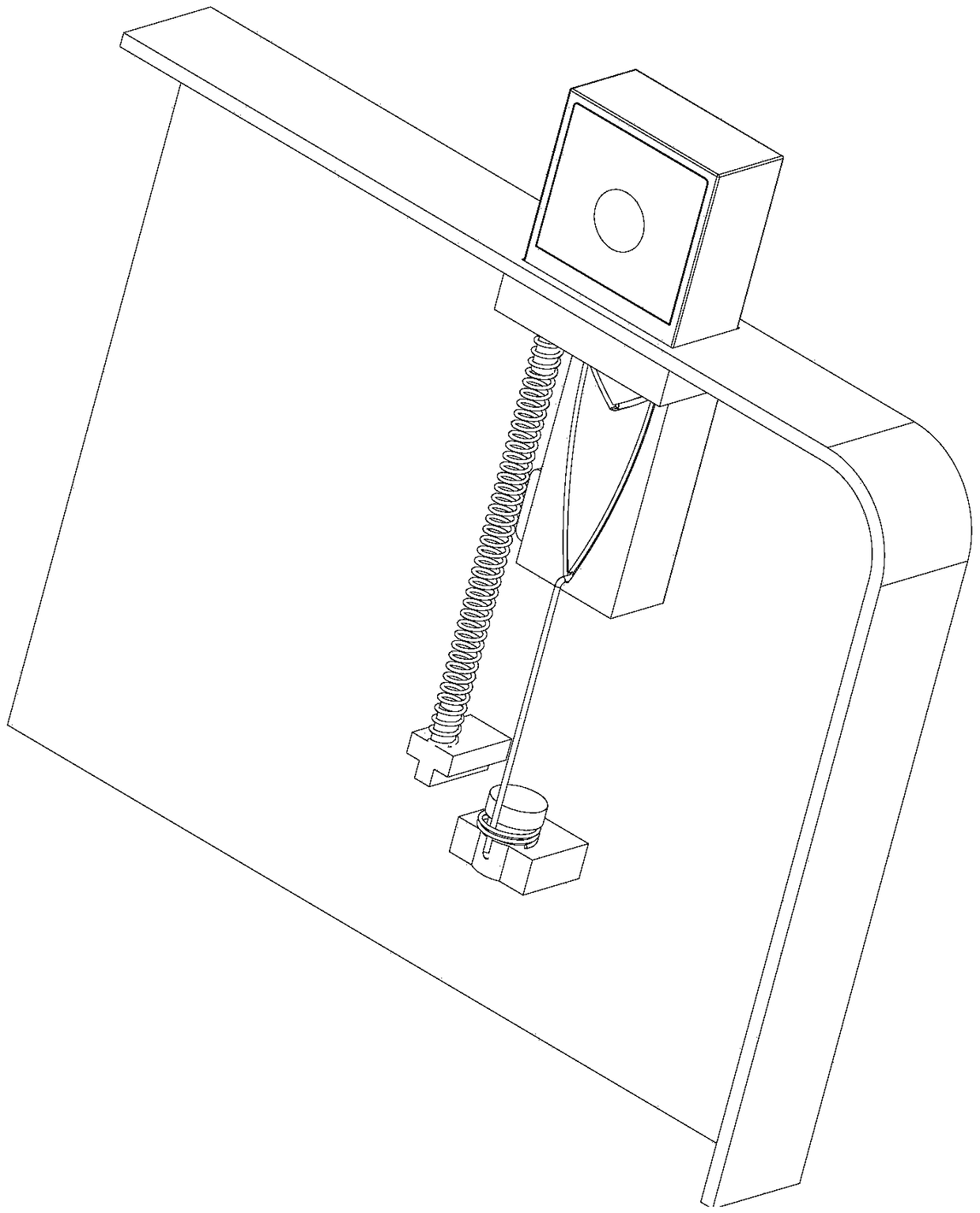
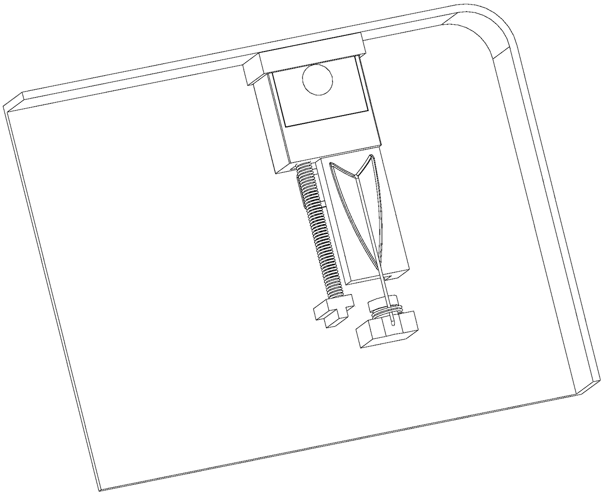
[0022] Please refer to Figure 1-Figure 5 , the embodiment of the present invention discloses a terminal device, and the disclosed terminal device includes a casing 100 , a camera 200 and a dri...


PUM


Abstract

The invention discloses terminal equipment. In the terminal equipment, the frame of a shell is provided with perforations, A camera is movably disposed on the housing, and has a retraction stroke andan ejection stroke relative to the housing, The driving mechanism comprises a first elastic part and an elastic hook, wherein the camera head is provided with a guide rail, the guide rail is providedwith an articulation part, the first end of the elastic hook is connected with the housing, the second end is slidably matched with the guide rail, the elastic hook can exert a pulling force on the camera head, and the first elastic part can exert an elastic force on the camera head, and the elastic force is opposite to the pulling force direction; Within the retraction stroke, the pulling force is greater than the elastic force, the second end of the elastic hook slides into the articulation part and is articulated with the articulation part, and the camera moves into the housing; During theejection stroke, the elastic force is greater than the tensile force, the second end of the elastic hook slides out of the hitch, and the camera moves out of the housing through the perforation. The scheme can solve the problems of high cost and complex structure of the current terminal equipment.

Description

technical field [0001] The invention relates to a terminal device. Background technique [0002] With more and more functions of terminal devices (such as mobile phones and tablet computers), more and more functional devices are configured on terminal devices, such as cameras, face recognition modules, and environmental photosensitive modules. Assembly presents great challenges. With the improvement of users' demand for the appearance of terminal equipment, users are increasingly favoring terminal equipment with a large screen-to-body ratio. Under the premise that the size of the whole machine is determined, the larger and larger screen-to-body ratio will lead to the board installed in the terminal equipment in the past. There is not enough space for the functional devices on the surface. [0003] In order to increase the screen-to-body ratio of the terminal device, the current camera of the terminal device is a retractable camera, and the retractable camera is driven by a...

Claims


Application Information

Patent Timeline
IPC IPC(8): H04M1/02H04N5/225
CPCH04M1/026H04M1/0264H04N23/57
Inventor 薛飞
Owner VIVO MOBILE COMM HANGZHOU CO LTD
Learn More