
A bi-directional self-locking rotary magnetic holder

A two-way self-locking, rotary technology, applied in the field of electromagnets, can solve the problems of inappropriate miniaturization and light-weight systems, small driving torque of the magnetic retainer, unable to provide sufficient self-locking force, etc. The effect of large locking force and small electrical time constant

Inactive Publication Date: 2019-01-15
TIANJIN NAVIGATION INSTR RES INST
View PDF8 Cites 0 Cited by
  • Summary
  • Abstract
  • Description
  • Claims
  • Application Information

AI Technical Summary

Problems solved by technology

[0003] The purpose of the present invention is to make up for the deficiencies of the prior art, and to provide a two-way self-locking rotary magnetic retainer to solve the problem that the existing magnetic retainer has a small driving torque, is not suitable for miniaturization and light weight systems, and cannot Provide enough self-locking force and other issues

Method used


Image

  • A bi-directional self-locking rotary magnetic holder
  • A bi-directional self-locking rotary magnetic holder
  • A bi-directional self-locking rotary magnetic holder

Examples


Embodiment Construction

[0027] The embodiments of the present invention will be described in detail below in conjunction with the accompanying drawings. It should be noted that the embodiments are illustrative, not restrictive, and cannot limit the protection scope of the present invention.

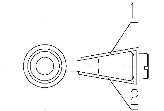
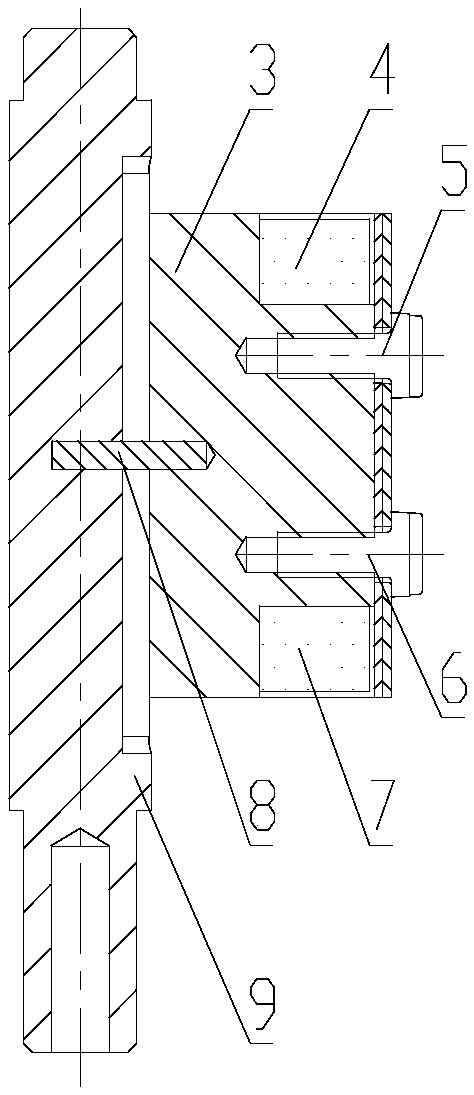
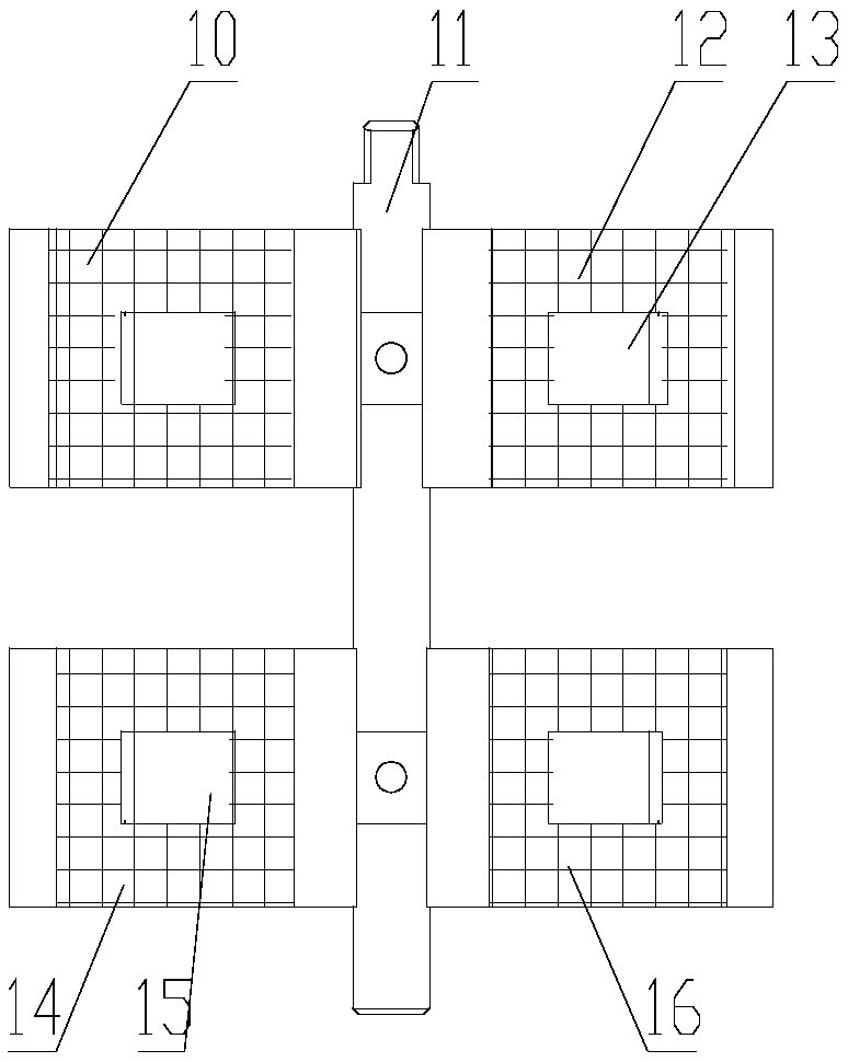
[0028] A bidirectional self-locking rotary magnetic retainer, the rotary magnetic retainer has a radial magnetic circuit structure. It includes an upper end cover 19, a lower end cover 23, a housing 21, a rotor and a stator. There are four flanges on the upper end cover 19 for connecting with external systems. The axis of the upper end cover is made with an installation through hole, and the bearing one 20 (constituting the upper end cover assembly) is installed in the installation through hole, and the axis of the lower end cover is made with a blind installation hole, and the bearing two 22 (constituting the lower end cover assembly). The upper end and the lower end of the casing are respectively connected an...


PUM


Abstract

The invention relates to a bi-directional self-locking rotary magnetic retainer, comprising an upper end cover, a lower end cover, a housing, a rotor and a stator. The upper end and the lower end of the housing are respectively connected with and installed with the upper end cover and the lower end cover. The rotor is composed of a shaft and a sleeve assembly, wherein the sleeve assembly is mounted on the shaft, the upper part and the lower part of the shaft are respectively rotatably connected with the upper end cover and the lower end cover through bearings, and the upper end of the shaft extends to the outer side of the upper end cover; The stator is installed between the upper end cover and the lower end cover. The invention is a bi-directional self-locking rotary magnetic holder withscientific design, reasonable structure, compact space structure and light weight. The product has a bi-directional power-off self-locking function, can play a better anti-vibration and anti-looseningeffect, and can meet the use requirements of a missile system.

Description

technical field [0001] The invention relates to the technical field of electromagnets, in particular to a bidirectional self-locking rotary magnetic holder. Background technique [0002] In fuze devices such as rockets and artillery shells, rotating magnetic holders are usually used to realize functions such as mechanical movement and limit protection, which requires electromagnets to have sufficient driving torque and two-way self-locking functions. At present, the traditional rotary magnetic retainer has problems such as small driving torque, low space utilization, and no self-locking force, which can no longer meet the needs of missile systems. Contents of the invention [0003] The purpose of the present invention is to make up for the deficiencies of the prior art, and to provide a two-way self-locking rotary magnetic retainer to solve the problem that the existing magnetic retainer has a small driving torque, is not suitable for miniaturization and light weight syste...

Claims


Application Information

Patent Timeline
Patent Type & Authority Applications(China)
IPC IPC(8): H02K1/12H02K1/22H02K3/28
CPCH02K1/12H02K1/22H02K3/28
Inventor 智豪王建飞潘龙飞井会所陈伟高向阳谭欣李学蛟侯巧芳
Owner TIANJIN NAVIGATION INSTR RES INST
Learn More