
Sampling time adaptive single-photon compression imaging control method and control device

A sampling time, compression imaging technology, applied in the field of weak light imaging, to achieve the effect of shortening sampling time, extending sampling time, and realizing sampling time self-adaptation

Active Publication Date: 2021-03-26
NANCHANG UNIV
View PDF5 Cites 0 Cited by
  • Summary
  • Abstract
  • Description
  • Claims
  • Application Information

AI Technical Summary

Problems solved by technology

In order to solve the above problems, photon counting compression imaging urgently needs a sampling time adaptive imaging method, and there is no report on the relevant scheme at present

Method used


Image

  • Sampling time adaptive single-photon compression imaging control method and control device
  • Sampling time adaptive single-photon compression imaging control method and control device
  • Sampling time adaptive single-photon compression imaging control method and control device

Examples


Embodiment 1

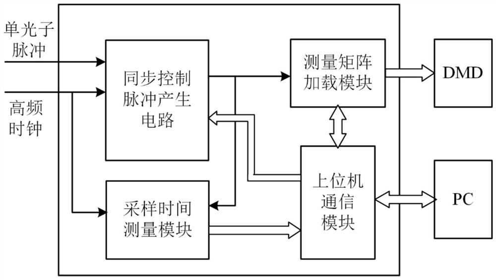
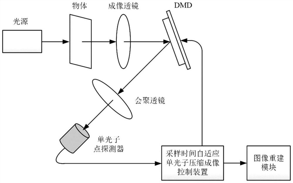
[0038] This embodiment is a specific implementation of the sampling time adaptive single-photon compression imaging control device, and its composition block diagram is as follows figure 1 As shown, it includes a PC host computer, a host computer communication module, a synchronous control pulse generation circuit, a sampling time measurement module, and a measurement matrix loading module; a high-frequency clock signal and a single photon pulse signal are input to the input terminal of the synchronous control pulse generation circuit, The output end of the synchronous control pulse generation circuit is connected to the measurement matrix loading module, the output of the measurement matrix loading module is connected to the DMD, the input of the sampling time measurement module is connected to the high-frequency clock signal and the output end of the synchronous control pulse generation circuit, and the sampling time measurement module The output of the upper computer is tran...

Embodiment 2

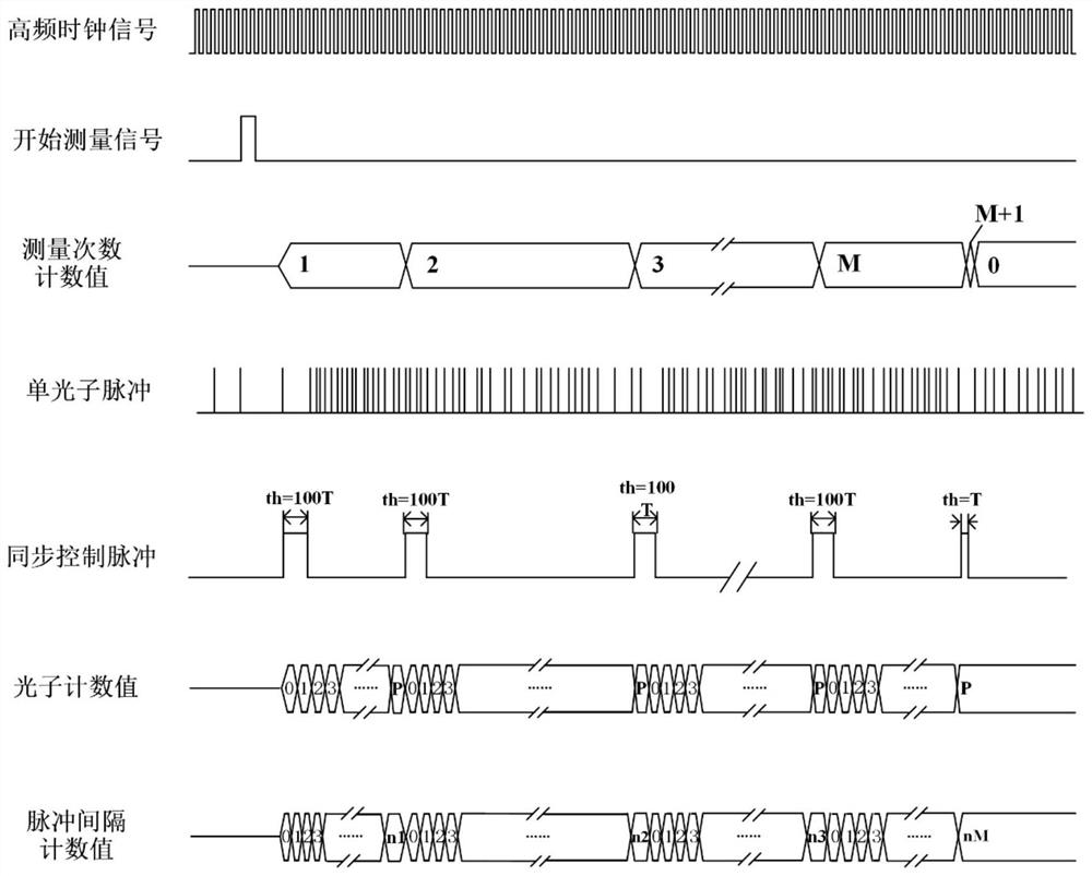
[0044] see figure 1 , figure 2 , this embodiment is a sampling time adaptive single-photon compression imaging control method, using the aforementioned sampling time adaptive single-photon compression imaging control device to realize single-photon compression imaging and use measured values ​​and measurement matrices to perform compressed sensing image reconstruction, the implementation steps as follows:

[0045] 1) Set the experimental parameters, and send an instruction to start the measurement;

[0046] 1.1) The PC host computer sends the experimental measurement times M and the counting threshold P to the synchronous control pulse generation circuit through the host computer communication module;

[0047]1.2) The PC upper computer sends the measurement matrix frame number M and the measurement matrix size P*Q to the measurement matrix loading module through the upper computer communication module;

[0048] 1.3) The PC host computer sends the measurement matrix generat...


PUM


Abstract

The invention relates to a control method and an apparatus for weak light imaging. A control method for sampling time adaptive single photon compression imaging comprises the steps of : setting experimental parameters, sending a command to start measurement; inputting a single photon pulse and a high frequency clock to a synchronous control pulse generating circuit to generate a synchronous control pulse, and inputting the synchronous control pulse to a sampling time measurement module and a measurement matrix loading module; the sampling time measurement module performing pulse interval measurement on the high frequency clock in a counting manner; the measurement matrix loading module loading a frame measurement matrix after detecting a rising edge of a synchronous control pulse signal, and sending the matrix to a PC host computer; the PC host computer reconstructing a compressed sensing image based on the received measurement matrix and the a pulse interval count. A control apparatusfor the sampling time adaptive single photon compression imaging comprises a PC host computer, a host computer communication module, the synchronous control pulse generating circuit, the sampling time measurement module and the measurement matrix loading module.

Description

technical field [0001] The invention relates to a weak light imaging technology, in particular to a control method and device for sampling time adaptive single-photon compression imaging in the field of weak light imaging. Background technique [0002] The method of using photon counting technology for extremely weak light imaging in photon counting imaging has broad application prospects in the fields of weak light detection such as deep space exploration, remote sensing imaging, and spectral measurement. In recent years, the application of compressed sensing in photon counting imaging has solved the problem that the pixel scale of high-precision single-photon array detectors is too small to meet the actual imaging needs, and the scanning time of point-by-point scanning is long, the efficiency of photon collection is low, and the system stability is low. And other issues. And the single-pixel imaging combined with compressed sensing and photon counting technology can colle...

Claims


Application Information

Patent Timeline
Patent Type & Authority Patents(China)
IPC IPC(8): G05B19/042
CPCG05B19/0423G05B2219/25257
Inventor 鄢秋荣王慧李冰袁成龙
Owner NANCHANG UNIV
Learn More