Fiber optic junction box with controllable incoming lines

A fiber optic junction box and cable inlet technology, applied in the field of junction boxes, can solve the problems of cumbersome and inconvenient, easy to cause accidents, and entanglement of incoming wires, so as to reduce the opening and closing time, reduce the difficulty of opening, and the opening structure is simple Effect

Active Publication Date: 2020-07-21
湖南率为控制科技有限公司
View PDF13 Cites 0 Cited by
  • Summary
  • Abstract
  • Description
  • Claims
  • Application Information

AI Technical Summary

Problems solved by technology

[0003] Most of the existing optical fiber junction boxes use the connection method of bolts and nuts to connect and fix the upper cover and the lower cover of the optical fiber junction box. Although the connection method of bolts and nuts is fastened, it is necessary to carry Many tools, plus the necessary tools for inspection, will be very cumbersome and inconvenient. In addition, there is no fixed structure for incoming lines in the existing optical fiber junction box. The number of incoming lines is usually very large. If there is no fixed structure inside the box It will cause the incoming wires to be entangled with each other, which not only prevents the maintenance personnel from performing investigations, but also easily causes accidents. Moreover, when the maintenance staff performs fiber splicing, they usually wrap the long incoming wires around the splice box to consume a few laps of length and then reconnect them. The incoming wires with just the right length are used for fusion splicing, but the incoming wires around the splice box will be loose due to a long time without a fixed wire slot, so that the incoming wires will be entangled again, which is likely to cause accidents

Method used


Image

  • Fiber optic junction box with controllable incoming lines
  • Fiber optic junction box with controllable incoming lines
  • Fiber optic junction box with controllable incoming lines

Examples


Embodiment Construction

[0022] The following will clearly and completely describe the technical solutions in the embodiments of the present invention with reference to the accompanying drawings in the embodiments of the present invention. Obviously, the described embodiments are only some, not all, embodiments of the present invention. Based on the embodiments of the present invention, all other embodiments obtained by persons of ordinary skill in the art without making creative efforts belong to the protection scope of the present invention.

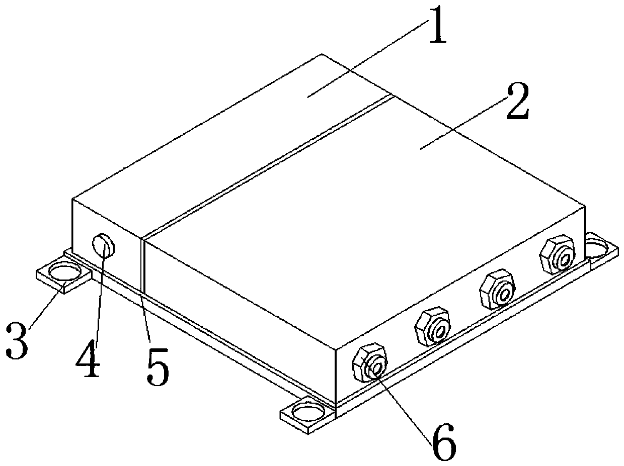
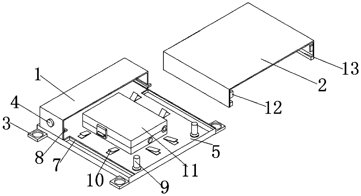
[0023] see Figure 1-6 , an optical fiber junction box that can control incoming lines, including a base plate 5, one end of the base plate 5 is fixedly connected with a fixed cover 1, and a pressing block 4 is arranged on the outside of the fixing cover 1, and a spring 21 is connected to the inner side of the pressing block 4, and The end of the spring 21 is connected with a fixed block 22, the outside of the spring 21 is connected with a connecting rod 23, a...


PUM


Abstract

The invention discloses an optical fiber junction box capable of controlling incoming lines, comprising a bottom plate. One end of the bottom plate is fixedly connected with a fixing cover. Pressing blocks are arranged on the outer side of the fixing cover. Springs are connected to the inner side of the pressing blocks. The ends of the springs are connected with fixing blocks. Connecting rods areconnected to the outer sides of the springs. Hook blocks are connected to the tail ends of the connecting rods. According to the optical fiber junction box capable of controlling incoming lines, the sliding connection structure of the optical fiber junction box can be achieved by arranging sliding grooves and sliding blocks, so that the optical fiber junction box is more convenient to use comparedwith conventional optical fiber junction boxes, and maintenance personnel do not need to carry a large number of tools to open and dismount when checking and maintaining, thus the opening difficultyof maintenance personnel in maintenance is reduced, the opening and closing time is reduced; the connecting structure of a fixing cover and a sliding cover is achieved through arranging the hook blocks and the blocking blocks; and the purpose of opening and closing of the fixing cover and the sliding cover is achieved by pressing the pressing blocks, so that the opening structure of the optical fiber junction box is simple, the sealing effect is good, the dismounting is convenient, and the junction box is suitable for household use.

Description

technical field [0001] The invention relates to the technical field of junction boxes, in particular to an optical fiber junction box capable of controlling incoming lines. Background technique [0002] In home decoration, the junction box is one of the electrical accessories, because the wires used for decoration pass through the wire tube, and the junction box is used as a transition at the joint of the wire (for example, the line is relatively long, or the wire tube needs to be cornered). Use, the wire tube is connected to the junction box, and the wires in the wire tube are connected in the junction box to protect the wires and connect the wires. This is the junction box. The general junction box is composed of a box cover, a box body, a terminal block, a diode, a connecting wire, and a connector, and an optical fiber junction box is a box for protecting the optical cable and the pigtail at the end of the laying of the optical cable. It is mainly used for indoor optical ...

Claims


Application Information

Patent Timeline
Patent Type & Authority Patents(China)
IPC IPC(8): G02B6/44
CPCG02B6/4446G02B6/4457
Inventor 陈友生
Owner 湖南率为控制科技有限公司
Why Eureka
Try Eureka