An optical cable transfer box for capacity expansion and transformation

A fiber optic cable transfer box and rotating connection technology, which is applied in the direction of optics, light guides, optical components, etc., can solve the problems of slow line collection efficiency, small selectable range, fixed position and height of optical cables, etc., to improve capacity, Wide range of options and easy-to-organize effects

Active Publication Date: 2022-07-15
金华市华阳通信器材有限公司
View PDF14 Cites 0 Cited by
  • Summary
  • Abstract
  • Description
  • Claims
  • Application Information

AI Technical Summary

Problems solved by technology

[0004] The purpose of the present invention is to solve the problem that the selectable range of the existing optical cable transfer box for the position and direction of the optical cable component lines passing through is relatively small, and the limitations of the optical cable component lines and handover are large; and multiple Different branch wires are easily entangled with each other when they are assembled in the transfer box, and it is not convenient to arrange and repair the optical cables in the transfer box; The splitting assembly of the optical cable is used for multi-directional adjustment, and the position of the assembly assembly inside the optical cable transfer box to collect the optical cable is not accurate and suitable; the position and height of the optical cable assembled in the transfer box are fixed and non-adjustable. It is very easy for the optical cables to be wound and mixed; the opening direction and position of the door on the optical cable transfer box are adjusted, causing the staff to transfer the optical cables in the optical cable transfer box and the efficiency of the collection is slow; Scratches and abrasions are prone to occur in the box, and a fiber optic cable transfer box for expansion and transformation is proposed

Method used


Image

  • An optical cable transfer box for capacity expansion and transformation
  • An optical cable transfer box for capacity expansion and transformation
  • An optical cable transfer box for capacity expansion and transformation

Examples


Embodiment Construction

[0040] The technical solutions of the present invention will be clearly and completely described below with reference to the embodiments. Obviously, the described embodiments are only a part of the embodiments of the present invention, rather than all the embodiments. Based on the embodiments of the present invention, all other embodiments obtained by those of ordinary skill in the art without creative efforts shall fall within the protection scope of the present invention.

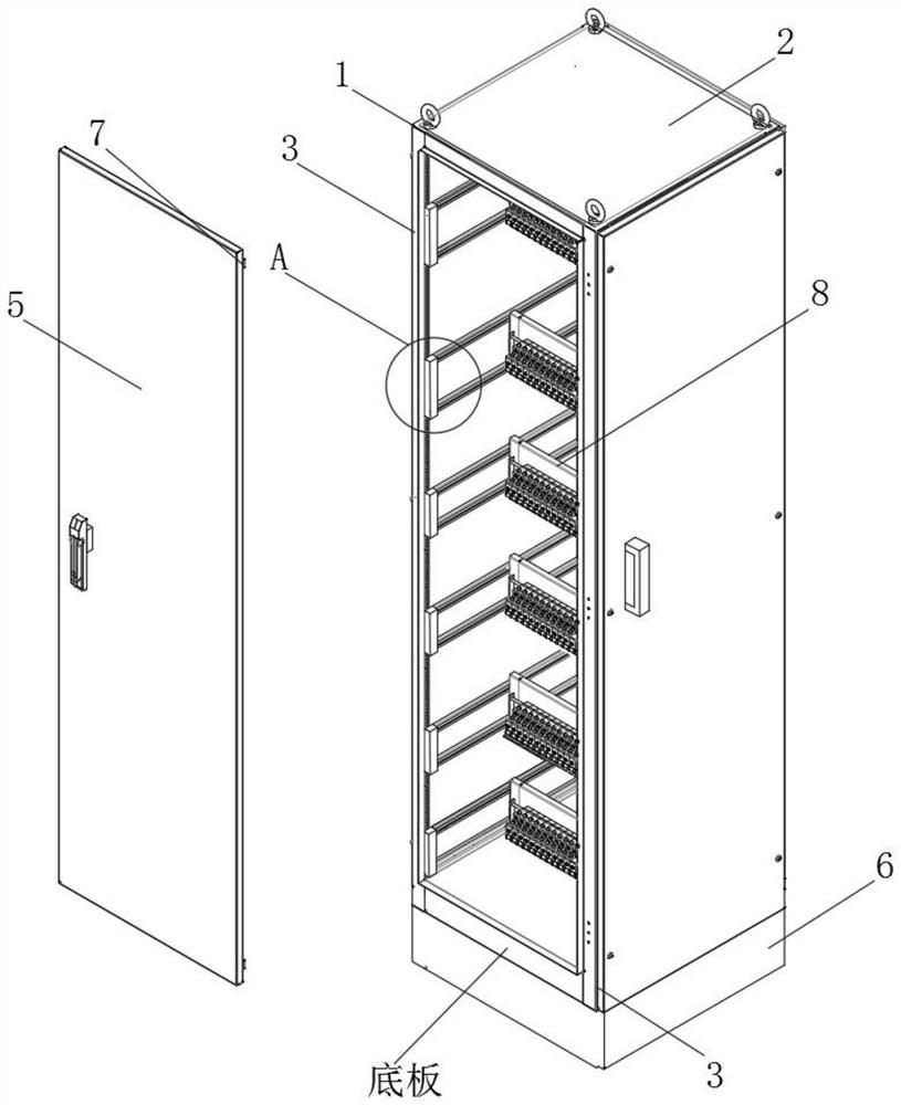
[0041] see Figure 1-9 As shown in the figure, an optical cable junction box for capacity expansion and transformation includes a top frame 1, a vertical rod 3, a motor 6 and a hub 8 of a cuboid structure. The top frame 1 is horizontally arranged on the top of the junction box, and the top frame 1 Upright poles 3 are arranged vertically under the four corners, and a bottom plate with a cuboid structure is vertically arranged at the bottom of the upright pole 3 , and a side flip door 4 is arranged between ...


PUM


Abstract

The invention discloses an optical cable transfer box for capacity expansion and transformation, comprising a top frame, a vertical pole, a motor 1 and a wiring rack in a rectangular structure. The top frame is horizontally arranged on the top of the transfer box, and the four corners of the top frame are all under A vertical pole is arranged vertically, and a bottom plate of a rectangular parallelepiped structure is vertically arranged at the bottom of the vertical pole. The beneficial effects of the present invention are: the second motor drives the second gear in the rolling groove 1 to cooperate with the first rack to roll, so as to adjust the height of the cross bar and the hub, and the third motor on the hub drives the third gear in the second roller groove. Rolling, thereby driving the front and rear adjustment activities of the hub, and a plurality of sub-assemblies can be set on the sleeve shaft through the sliding The junction box can adjust and use the branch components of the optical fiber cable in multiple directions, so as to ensure that the position of the branch components to connect the optical cables is more accurate and suitable.

Description

technical field [0001] The invention relates to an optical cable transfer box, in particular to an optical cable transfer box for capacity expansion and reconstruction, and belongs to the technical field of optical cable transfer box applications. Background technique [0002] Optical cable transfer box is a transfer equipment that provides optical cable end, optical cable splitting and jumper for optical cable group. The optical cables are integrated and loaded in the optical cable transfer box, which is convenient for shunting, handing over and sorting out different optical cable groups. [0003] The existing optical cable junction box still has many deficiencies in use. The limitation of handover is large, and multiple different branch lines are easily entangled with each other when they are assembled in the transfer box, which is not convenient for sorting and maintenance of optical cables in the transfer box, and the capacity of the transfer box for the optical cable g...

Claims


Application Information

Patent Timeline
Patent Type & Authority Patents(China)
IPC IPC(8): G02B6/44
CPCG02B6/4446G02B6/4452
Inventor 王加齐
Owner 金华市华阳通信器材有限公司
Why Eureka
Try Eureka