
Monitoring camera

A monitoring camera and camera technology, applied in the field of monitoring cameras, can solve problems such as limited camera shooting angles, limited camera shooting angles, monitoring dead angles, etc., and achieve the effect of reducing monitoring dead angles

Active Publication Date: 2019-01-15
荣成歌尔科技有限公司
View PDF7 Cites 2 Cited by
  • Summary
  • Abstract
  • Description
  • Claims
  • Application Information

AI Technical Summary

Problems solved by technology

[0002] Surveillance equipment is of great value for production control and safety and explosion protection. However, for the surveillance cameras currently on the market, the cameras that capture images are usually only fixed installations, so the orientation of the camera is fixed and can only be directed in the direction that the camera is aimed at. Shooting, the picture behind or on the side of the camera cannot be taken, which limits the shooting angle of the camera, and there is a monitoring dead angle
Moreover, because the camera itself has a certain field of view, even for the direction the camera is aimed at, the shooting angle of the camera is limited, which exacerbates the problem of monitoring dead angles in shooting

Method used


Image

  • Monitoring camera
  • Monitoring camera
  • Monitoring camera

Examples


Embodiment Construction

[0032] In order to make the object, technical solution and advantages of the present invention clearer, the implementation manner of the present invention will be further described in detail below in conjunction with the accompanying drawings.

[0033] In the description of this application, it should be noted that the terms "center", "upper", "lower", "left", "right", "vertical", "horizontal", "inner", "outer" etc. The indicated orientation or positional relationship is based on the orientation or positional relationship shown in the drawings, and is only for the convenience of describing the present application and simplifying the description, rather than indicating or implying that the referred device or element must have a specific orientation, use a specific orientation construction and operation, therefore should not be construed as limiting the application. In addition, the terms "first", "second", and "third" are used for descriptive purposes only, and should not be co...


PUM


Abstract

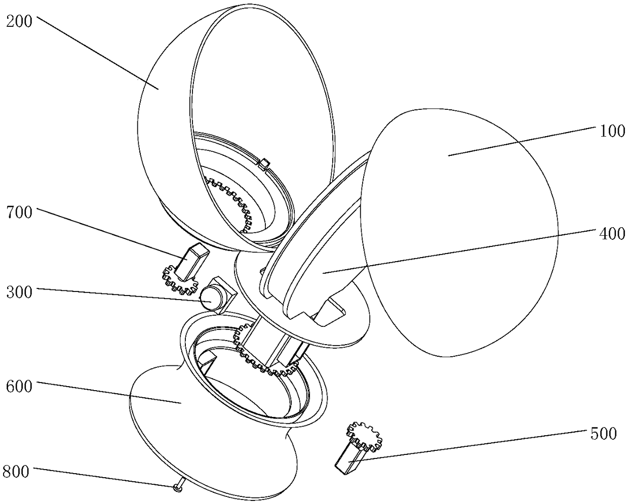
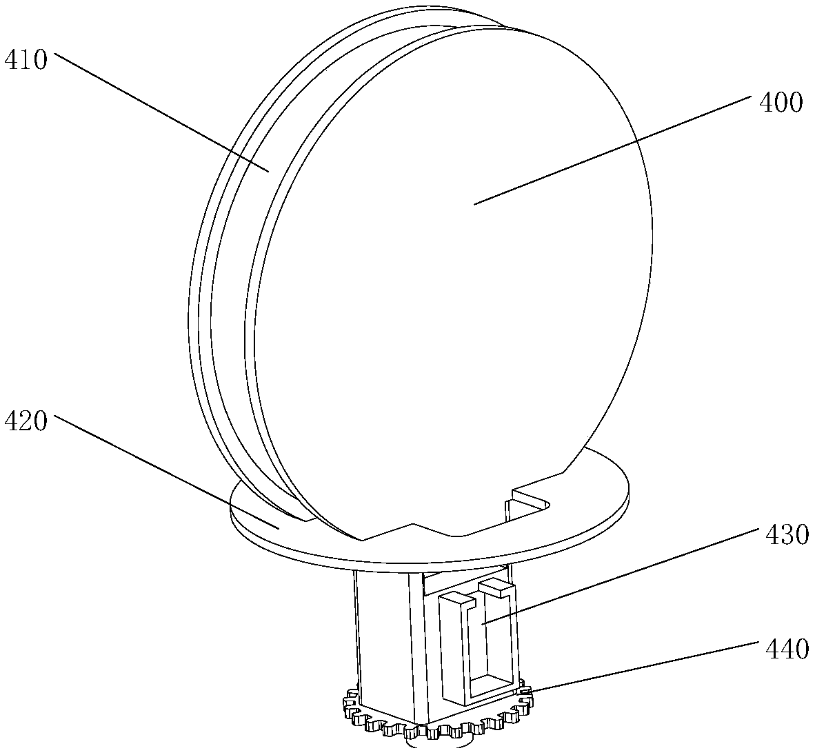
The invention discloses a monitoring camera. The monitoring camera comprises an upper shell, a lower shell, a camera body, a bracket, a first driving device and a second driving device. The camera body is positioned in the upper shell and is slidably arranged along an arc-shaped sliding rail in the vertical direction of the bracket. A guide rail which is inclined relative to the vertical directionis arranged on the inner wall of the upper shell. The first driving device drives the upper shell to horizontally rotate relative to the bracket, and under the guide action of the guide rail, the camera body turns to shoot along the arc-shaped sliding rail in the vertical direction. The second driving device drives the bracket and the upper shell to rotate horizontally relative to the lower shell, so that the camera body turns to shoot in the horizontal direction. According to the monitoring camera, when the upper shell rotates relative to the bracket, the inclined guide rail on the inner wall of the upper shell guides the camera body to slide along the vertical arc-shaped sliding rail of the bracket, so that the turning to shoot in the vertical direction is realized; and when the bracketand the upper shell integrally rotate horizontally relative to the lower shell, turning to shoot in the horizontal direction can be realized, and dead angles of shooting by the camera body are reduced.

Description

technical field [0001] The invention relates to the technical field of monitoring equipment, in particular to a monitoring camera. Background technique [0002] Surveillance equipment is of great value for production control and safety and explosion protection. However, for the surveillance cameras currently on the market, the cameras that capture images are usually only fixed installations, so the orientation of the camera is fixed and can only be directed in the direction that the camera is aimed at. For shooting, the pictures behind or on the side of the camera cannot be captured, which limits the shooting angle of the camera, and there is a monitoring dead angle. Moreover, since the camera itself has a certain field of view, even for the direction the camera is aimed at, the shooting angle of the camera is limited, thus exacerbating the problem of monitoring dead angles in shooting. Contents of the invention [0003] In view of the problem of monitoring blind spots in...

Claims


Application Information

Patent Timeline
IPC IPC(8): F16M11/10F16M11/08H04N5/225
CPCF16M11/08F16M11/10H04N23/50
Inventor 兰向东
Owner 荣成歌尔科技有限公司
Learn More