
Template demoulding device for building site

A construction site and formwork technology, applied in the direction of construction, building structure, and on-site preparation of building components, can solve problems such as wall damage, achieve the effects of reducing rigid contact, protecting integrity and aesthetics, and saving manpower

Active Publication Date: 2019-01-15
中湾建设集团有限公司
View PDF4 Cites 2 Cited by
  • Summary
  • Abstract
  • Description
  • Claims
  • Application Information

AI Technical Summary

Problems solved by technology

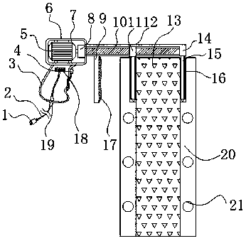
[0004] Based on the simple structure of the formwork removal device and the technical problem that it is easy to cause damage to the wall during disassembly, the invention proposes a formwork removal device for construction sites

Method used


Image

  • Template demoulding device for building site
  • Template demoulding device for building site
  • Template demoulding device for building site

Examples


Embodiment Construction

[0025] The following will clearly and completely describe the technical solutions in the embodiments of the present invention with reference to the accompanying drawings in the embodiments of the present invention. Obviously, the described embodiments are only some, not all, embodiments of the present invention.

[0026] In describing the present invention, it should be understood that the terms "upper", "lower", "front", "rear", "left", "right", "top", "bottom", "inner", " The orientation or positional relationship indicated by "outside", etc. is based on the orientation or positional relationship shown in the drawings, and is only for the convenience of describing the present invention and simplifying the description, rather than indicating or implying that the referred device or element must have a specific orientation, so as to Specific orientation configurations and operations, therefore, are not to be construed as limitations on the invention.

[0027] refer to Figure ...


PUM


Abstract

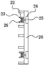
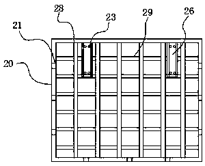
The invention relates to a template demoulding device for building site, belongs to the technical field of buildings, and aims at solving the problem that walld tend to be damaged during dismounting.The template demoulding device comprises a motor casing, a handle is in threaded connection to one side of the bottom of the motor casing, a first through hole is formed in one side of the handle, theinternal of the first through hole is in threaded connection with a starting switch, a second through hole is formed in the bottom of the handle, and the internal of the second through hole is in clamp connection with a wire protective rubber sleeve. Each dismounting plate is inserted into a T-shaped notch, a controller controls a motor to rotate via the starting switch, the motor drives a threaded rod to rotate via a differential, and further drives a slide block on the threaded rod to move, outward stress is applied to the two dismounting plates, and a steel template is dismounted from theconcrete wall; and it is not required to implement dismounting via a crowbar by workers, the concrete wall is kept complete and beautiful, and labor is saved.

Description

technical field [0001] The invention relates to the technical field of formwork engineering, in particular to a formwork removal device for construction sites. Background technique [0002] Formwork engineering refers to the formwork formed by newly poured concrete and a complete set of structural system to support the formwork. Among them, the structural part that contacts the concrete and controls the predetermined size, shape, and position is called the formwork, and the rods, trusses, couplings, etc. that support and fix the formwork. Metal accessories, working bridges, etc. constitute the supporting system. For sliding formwork and self-elevating formwork, lifting power, lifting frame, platform and other components are added. Formwork engineering is a temporary structure in concrete construction. In the field of modern building construction, with the development of high-rise buildings, long-span buildings and large-scale special structures, in order to speed up the cons...

Claims


Application Information

Patent Timeline
IPC IPC(8): E04G19/00
CPCE04G19/00
Inventor 刘小平
Owner 中湾建设集团有限公司
Learn More