A functional testing device

A technology for functional testing and equipment, applied in the directions of transportation and packaging, conveyor objects, etc., can solve the problems of low productivity and output of functional testing equipment, large area of ​​functional testing equipment, and complex structure of functional testing equipment, etc. Time consumption, improve fluency, and ensure the effect of positioning accuracy

Active Publication Date: 2021-01-05
UNIVERSAL SCIENTIFIC INDUSTRIAL (SHANGHAI) CO LTD
View PDF6 Cites 0 Cited by
  • Summary
  • Abstract
  • Description
  • Claims
  • Application Information

AI Technical Summary

Problems solved by technology

But the existing electronic product functional testing equipment has the following disadvantages: (1) the functional testing equipment occupies a large area and the space utilization rate is small, which causes the electronic product manufacturer to invest a lot in the factory construction area for producing electronic products. Under the premise that electronic products are updated too fast, it will undoubtedly lead to excessive investment capital of manufacturers, which seriously restricts the development of manufacturers; (2) functional testing equipment needs to be shut down for loading and unloading, which reduces its output and production capacity; (3) functional The complex structure of the test equipment makes the walking route of the robot arm too curved, which wastes product handling time, and thus lowers the production capacity and output of the functional test equipment; (4) Errors occur when the robot arm positions the product, which wastes product handling time, resulting in lower capacity and output of functional test equipment

Method used


Image

  • A functional testing device
  • A functional testing device
  • A functional testing device

Examples


Embodiment Construction

[0062] In order to more clearly illustrate the embodiments of the present invention or the technical solutions in the prior art, the specific implementation manners of the present invention will be described below with reference to the accompanying drawings. Obviously, the accompanying drawings in the following description are only some embodiments of the present invention, and those skilled in the art can obtain other accompanying drawings based on these drawings and obtain other implementations.

[0063] In order to make the drawing concise, the parts related to the present invention are only schematically shown in each drawing, and they do not represent the actual structure of the product. In addition, to make the drawings concise and easy to understand, in some drawings, only one of the components having the same structure or function is schematically shown, or only one of them is marked. Herein, "a" not only means "only one", but also means "more than one". In this arti...


PUM


Abstract

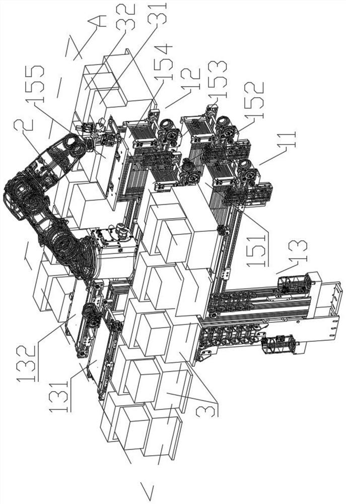
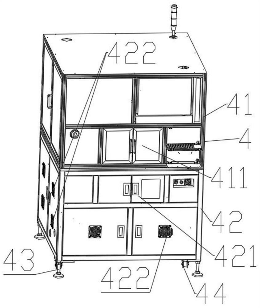
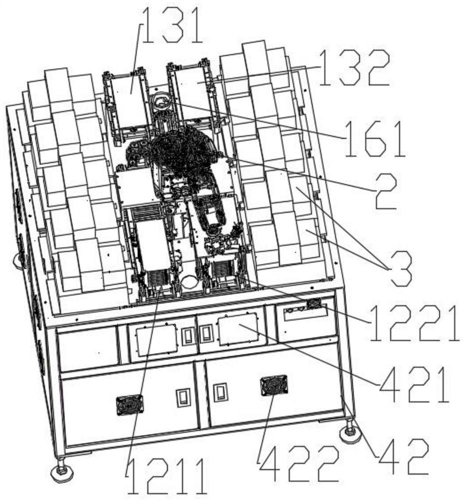
The invention discloses functional testing equipment. The equipment comprises a feeding and discharging system, a mechanical arm and at least one functional testing jig. The functional testing jigs are distributed on the two sides of the mechanical arm and located within the working range of the mechanical arm. The feeding and discharging system comprises a first conveying mechanism group and a second conveying mechanism group which are arranged in a second direction in parallel, and a third conveying mechanism group which is arranged in the second direction, wherein a first direction is perpendicular to the second direction; a butt-joint mechanism of the third conveying mechanism group in a first position is in butt joint with a first butt-joint end; a butt-joint mechanism of the third conveying mechanism group in a second position is in butt joint with a second butt-joint end; and a plane where a third position of the third conveying mechanism group is located is flush with testing planes of the functional testing jigs. The functional testing equipment is small in occupied area and high in space utilization rate; feeding and discharging can be achieved without needing equipment stop, and a 24 h uninterrupted work mode can be achieved; the travelling path of the mechanical arm is optimized; and the capacity and the output of the equipment are greatly increased.

Description

technical field [0001] The invention relates to the technical field of electronic product function test equipment, in particular to a function test equipment. Background technique [0002] Due to the rapid development of the Internet and the Internet of Things, the cycle of innovation and replacement of electronic products is getting shorter and shorter. The performance of electronic products, especially smart products, is the guarantee that determines their market value and market share. At the same time, in order to meet the increasing needs of users, various functional tests before entering the market are an important guarantee to ensure the performance of electronic products. But the existing electronic product functional testing equipment has the following disadvantages: (1) the functional testing equipment occupies a large area and the space utilization rate is small, which causes the electronic product manufacturer to invest a lot in the factory construction area for...

Claims


Application Information

Patent Timeline
Patent Type & Authority Patents(China)
IPC IPC(8): B65G47/90
CPCB65G47/90
Inventor 曾耀興李冠儒沈霞
Owner UNIVERSAL SCIENTIFIC INDUSTRIAL (SHANGHAI) CO LTD
Why Eureka
Try Eureka