A low energy consumption catamaran structure

A catamaran, low energy consumption technology, applied in the marine field

Active Publication Date: 2020-10-27
NINGBO UNIV
View PDF5 Cites 0 Cited by
  • Summary
  • Abstract
  • Description
  • Claims
  • Application Information

AI Technical Summary

Problems solved by technology

[0003] In order to solve the problem of a large amount of energy waste caused by turbulence and ship waves generated during ship navigation, and reduce wave-making resistance, the invention provides a low-energy catamaran structure

Method used


Image

  • A low energy consumption catamaran structure
  • A low energy consumption catamaran structure
  • A low energy consumption catamaran structure

Examples


Embodiment 1

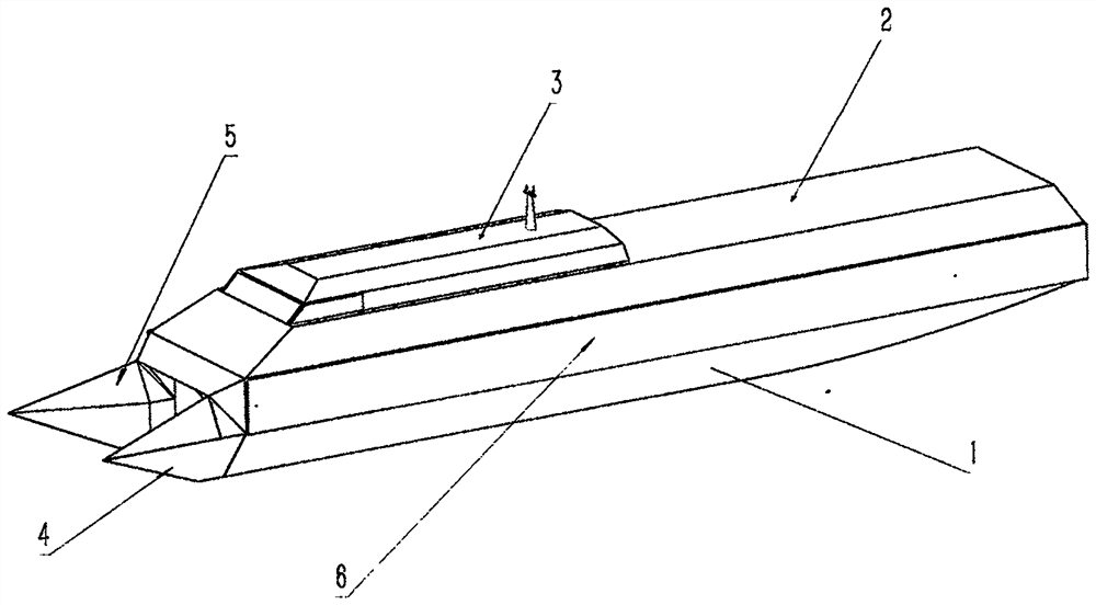
[0024] The two hulls 1 of the low-energy catamaran described in the present invention and the tip diverters 4 of the two bows are all straight plates on the outside.

[0025] The two hulls 1 of a low-energy catamaran described in the present invention are symmetrical to the longitudinal vertical center plane of the total hull; The inner inclined straight board 1-3, and the outer two vertical straight boards 1-1 are parallel to each other.

[0026] The bows of the two hulls 1 are all arranged as triangular cone-shaped tip water diversion heads 4, and the outer triangular surface 4-1 is on the same plane as the straight plate 1-3 on the outside of the hull that is inclined to the inner side of the ship bottom.

[0027] The two hulls 1 of the low-energy catamaran and the tip diverters 4 of the two bows are all straight plates on the outside, and its effect is that when the catamaran is sailing forward, the hull does not discharge water to the outside of the two sides of the hull....

Embodiment 2

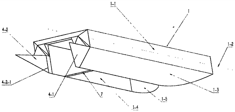
[0029] The inner sides of the two hulls 1 of the low-energy catamaran structure of the present invention are vertical straight plates 1-4 and smooth curved plates 1-5, and the inner triangular surface 4-2 of the tip diverter 4 of the bow is vertical. Straight inward sloped setting.

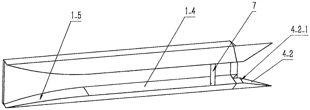
[0030] On the inside of the hull of the two hulls 1, the main body part of the hull is set as a vertical straight plate 1-4, and the stern part is set as a smooth curved plate 1-5 that is vertical but curved to the outside of the tail of the hull.

[0031] The bows of the two hulls 1 are all set to a triangular cone-shaped tip water diversion head 4, the inner triangular surface 4-2 is vertical but inclined to the center of the hull to the stern, and the bottom edge 4-2- of the triangular surface 4-2 1 is seamlessly connected with the vertical straight plate 1-4 on the inside of the hull.

[0032] The shape of the inside of the hull of the two hulls 1 of the low-energy catamaran is set and the sh...

Embodiment 3

[0034] The two bows of the two hulls 1 of the low-energy catamaran structure described in the present invention are all set as tip water diversion heads 4, and the sharp angle 4-4 of each tip water diversion head 4 is 19.5°. The bottom frame between the two hulls 1 is provided with a horizontally placed turbulence guide plate 7 .

[0035] The two bows of the low-energy catamaran structure are tip subheads 4, and the forward sharp angle 4-4 of the horizontal triangular plane 4-3 at the upper end of each tip subhead 4 is set to 19.5°. It is the turbulent flow and v-shaped ship traveling waves generated after the water is drained from the inner triangular surface 4-2 of the tip water diversion head 4, which can be assembled and superimposed to form the largest wave crest.

[0036] The bottom frame between the two hulls 1 of the low-energy catamaran is provided with a horizontally placed turbulence deflector 7, the front edge of the turbulence deflector 7 is in the longitudinal di...


PUM


Abstract

A low energy consumption catamaran structure belongs to the field of shipbuilding, and solves the problem of turbulence generated to the outside of the ship hull and energy loss caused by the ship traveling wave when the ship is sail. The low energy consumption catamaran structure is characterized in that: two hulls are symmetrical, flat plates are arranged on the outside, the distance between thebow and the stern of the ship is equal to the distance between the outboard straight plates, a fluidic curved panel arranged as a vertical flat plate and bent outward to the stern are arranged at theinner sides of the two hulls, the two bow heads are provided with a tip diversion head with a sharp angle of 19.5 DEG, the outer triangular surface is coplanar with the outer straight plates of the hulls, the medial triangle slopes vertically to the stern, and 19.5 degree from that longitudinal horizontal distance L / 2ctg from the bow is provided with a turbulent guide plate. When a catamaran is sailing forward, the water discharged from the bow only flows to the inner side of the catamaran, and the velocity to the stern is increased through the turbulent guide plate, which assists the propulsion of the catamaran to increase the propulsion force, at the same time, the water pressure of the stern and stern is raised, the water pressure difference between the forward and stern of the catamaran is reduced, the wave-making resistance is reduced, and the speed is increased.

Description

technical field [0001] The invention relates to the field of ships, in particular to a catamaran structure with low energy consumption. Background technique [0002] When a ship sails on the water, it must be propelled by the propeller of the ship. The bow of the ship pushes the water in the forward direction to both sides. The pushed water forms a turbulent flow, and forms a V-shaped ship wave on both sides of the ship that spreads to both sides, forming The turbulent flow and ship waves have relatively large energy, resulting in a large loss of energy, which reduces the utilization rate of the effective energy of the ship's propeller; during the ship's navigation, due to the water pressure difference between the bow and the stern of the ship, the ship's wave-making resistance is generated, which hinders the The forward movement of the ship. Today, a catamaran is designed to reduce the intensity of the ship's traveling waves, and reuse the formed turbulence to improve the ...

Claims


Application Information

Patent Timeline
Patent Type & Authority Patents(China)
IPC IPC(8): B63B1/12B63B1/32
CPCB63B1/121B63B1/32Y02T70/10
Inventor 胡开鑫
Owner NINGBO UNIV
Why Eureka
Try Eureka