Welding fixture and welding method for ensuring flatness of hot chamber shell

A welding method and welding fixture technology, applied in welding equipment, welding equipment, auxiliary welding equipment, etc., can solve problems such as insufficient consideration of methods and measures to prevent welding deformation, poor box flatness, and unacceptable products.

Pending Publication Date: 2019-01-15
PINGHU HEQI HEAVY MACHINERY
View PDF10 Cites 1 Cited by
  • Summary
  • Abstract
  • Description
  • Claims
  • Application Information

AI Technical Summary

Problems solved by technology

[0007] (3) Welding: direct welding, methods and measures to prevent welding deformation are not fully considered
[0008] The above problems cause the flatness of the box to be too poor after the welding of the hot chamber shell box is completed, and the product is often not accepted in the end.

Method used


Image

  • Welding fixture and welding method for ensuring flatness of hot chamber shell
  • Welding fixture and welding method for ensuring flatness of hot chamber shell
  • Welding fixture and welding method for ensuring flatness of hot chamber shell

Examples


Embodiment 1

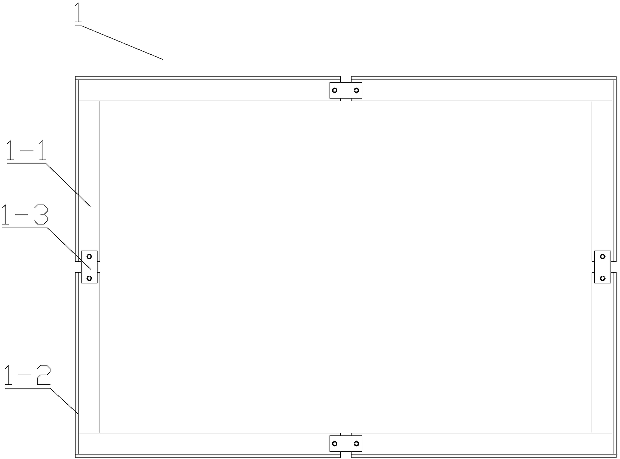
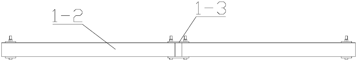
[0030] Such as figure 1 , figure 2 , image 3 , Figure 4 As shown, a welding fixture for ensuring the flatness of the heat chamber shell described in this embodiment includes an inner tire frame 1 placed inside the heat chamber shell and an outer tire frame 2 placed outside the heat chamber shell, the inner tire frame The structure of 1 includes a square tube 1-1, a backing plate 1-2 and a No. 1 connecting plate 1-3. Every two square tubes 1-1 form an L-shaped structure by welding the ends, and four L-shaped structures are butted end to end to form Rectangular structure, a No. 1 connecting plate 1-3 is arranged on the L-shaped structure butted head to tail, and the No. 1 connecting plate 1-3 and the L-shaped structure are connected by bolts, and after being connected through the No. 1 connecting plate 1-3 There is a gap between the L-shaped structures, and a layer of backing plate 1-2 is pasted on the periphery of the four L-shaped structures forming a rectangular structu...

Embodiment 2

[0032] Such as Figure 5 , Figure 6 , Figure 7 , Figure 8 As shown, this embodiment describes a welding method using the welding fixture described in Embodiment 1 to ensure the flatness of the heat chamber shell, and the specific steps are as follows:

[0033] (1), place a plurality of temporary pads 5 on a flat and horizontal platform 6, place the first inner tube frame 1 horizontally on the temporary pad 5, and place several temporary pads on the first inner tube frame 1 Block 5, then place the second inner tube frame 1, adjust the position of the second inner tube frame 1 to ensure that the projections of the two inner tube frames 1 on the platform 6 are completely coincident;

[0034] (2), set the A part 3 and the B part 4 of the heat chamber shell on the inner tire frame 1;

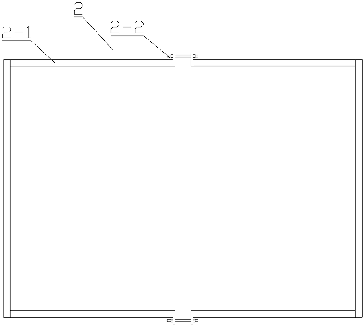
[0035] (3), two outer tire frames 2 are sleeved outside the hot chamber shell, and the two U-shaped structures of each outer tire frame 2 are distributed on the outside of the hot chamber shel...


PUM

PropertyMeasurementUnit
thicknessaaaaaaaaaa

Abstract

The invention relates to the technical field of heat chamber shell processing, in particular to a welding fixture for ensuring the flatness of the heat chamber shell. The fixing fixture comprises an inner tube frame disposed inside the hot chamber housing and an outer tube frame disposed outside the hot chamber housing. The welding method comprises following steps: (1) setting two inner tube frames on the platform and ensuring that the projections of the two inner tube frames on the platform are completely coincident; (2) a part A and a part B of the heat chamber shell are sleeved on the innertube frame; (3) two outer tube frames are sleeved on the exterior of the heat chamber shell; (4) deformation prevention is performed on the A and B parts of the heat chamber shell before welding; (5)manual argon arc welding is used to weld the butt wire of the hot chamber shell. The invention provides a welding fixture and a welding method for ensuring the flatness of a hot chamber shell, whichare improved from three aspects of an assembly mode, a tooling and welding deformation prevention, so as to solve the problem that the flatness of the hot chamber shell box is over-poor.

Description

technical field [0001] The invention relates to the technical field of heat chamber shell processing, in particular to a welding fixture and a welding method for ensuring the flatness of a heat chamber shell. Background technique [0002] The hot chamber shell of the inspection center is an important nuclear test equipment. It is a large box structure with a size of 5 meters x 3.5 meters x 3 meters, a wall thickness of only 3 mm, and a material of 321 stainless steel. It is a typical Large-size stainless steel thin-walled parts, from the perspective of use, require high flatness, error requirements ≤ 3mm / 3m, and high precision. Due to the large size of the box and the thin wall thickness, the rigidity is poor, and the plate is easy to misalign when assembling; the box size is large, the wall thickness is thin, and it is made of stainless steel, which is prone to angular deformation and wave deformation during welding. Due to these structural features of the product, it is d...

Claims


Application Information

Patent Timeline
Patent Type & Authority Applications(China)
IPC IPC(8): B23K37/04B23K31/00B23K9/16
CPCB23K9/0026B23K9/16B23K31/003B23K37/0443
Inventor 范留华张孝平马紫阳
Owner PINGHU HEQI HEAVY MACHINERY
Why Eureka
Try Eureka