
An essence adding device used for chrysanthemum flower processing

A technology of chrysanthemum processing and adding devices, which is applied in the direction of feeding devices, chemical instruments and methods, chemical/physical processes, etc. It can solve the problem of excessive or excessive use of additives, poor control of additives, and impact on product quality, etc. problem, to achieve the effect of easy dose control, good practical effect and convenient operation

Inactive Publication Date: 2019-01-15
临泉县同鑫达农业有限公司
View PDF1 Cites 2 Cited by
  • Summary
  • Abstract
  • Description
  • Claims
  • Application Information

AI Technical Summary

Problems solved by technology

[0004] The above-mentioned technical solution also has the following defects in actual use: the amount of additives cannot be well controlled when adding additives, so it often results in excessive or insignificant use of additives, which affects product quality

Method used


Image

  • An essence adding device used for chrysanthemum flower processing
  • An essence adding device used for chrysanthemum flower processing
  • An essence adding device used for chrysanthemum flower processing

Examples


Embodiment 1

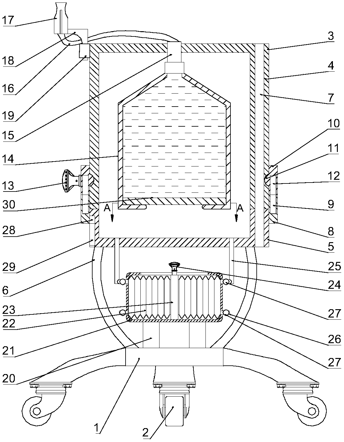
[0024] A flavor adding device for chrysanthemum processing, please refer to figure 1 with 3 , Including the support seat 1, the upper part of the support seat 1 is provided with a pressurized housing 3, the pressurized housing 3 is composed of an upper half 4 and a lower half 5, and the side walls of the upper half 4 and the lower half 5 are internally fixed A rotating cylinder 7 is embedded. A movable sleeve 8 is sleeved on the outside of the contact point between the upper half 4 and the lower half 5, and the upper side wall of the upper half 4 is fixed through the outer thread sleeve 15 and the outer thread The bottom end of the sleeve 15 is connected with the liquid inlet end of the liquid storage tank 14 through threads. The lower side wall of the liquid storage tank 14 is provided with a through hole. The liquid storage tank 14 is provided with a piston plate 30. The upper part is connected with the spray head 17 through a bellows. The lower part of the support base 1 is p...

Embodiment 2

[0027] On the basis of Example 1, please refer to figure 1 with 2 , The wall of the lower half 5 is provided with a notch 29, the inner wall of the movable sleeve body 8 is fixedly connected with a movable block 28, the movable block 28 is located in the notch 29, and the movable sleeve body 8 is evenly fixed and embedded with a number of iron magnets. A9, the magnetic south pole and the magnetic north pole of the adjacent iron magnet A9 are opposite to each other. The upper side of the movable sleeve body 8 is provided with a rotating sleeve body 10, the inner middle of the rotating sleeve body 10 is integrally formed with a protrusion 11, and the outer wall of the upper half 4 There is a notch that fits the protrusion 11, and a number of magnets B12 are evenly embedded in the interior of the rotating sleeve body 10. The magnetic south and north poles of the adjacent magnets B12 are in opposite directions, and the magnets A9 and B12 are both ferrite. Magnet, the side wall of th...


PUM


Abstract

The invention discloses an essence adding device used for chrysanthemum flower processing, and relates to the technical field of crop processing. The device includes a supporting seat. A pressurizingshell is disposed above the supporting seat and includes an upper half part and a lower half part. A rotating cylinder is fixedly embedded into the side walls of the upper half part and the lower halfpart. A contact part of the upper and lower half parts is sleeved with a movable sleeve. An external-thread sleeve penetrates the upper side wall of the upper half part fixedly. When liquid essence in a liquid storage tank is to be injected into a processing step, a push-and-pull handle is moved manually to gradually increase pressure in the pressurizing shell so that a piston plate moves upward,and therefore, the liquid essence passes through a corrugated pipe and is finally sprayed out through a sprayer, the adding process of the liquid essence can be continuously operated, the dosage canbe controlled easily, and the device has good practical effects.

Description

Technical field [0001] The invention relates to the technical field of crop processing, in particular to a flavor adding device for chrysanthemum processing. Background technique [0002] Chrysanthemum is rich in flavonoids, vitamins, trace elements, amino acids and other substances, which have anti-pathogen, enhance capillary resistance, anti-oxidation and anti-aging effects. [0003] The Chinese patent with the authorized announcement number CN207805547U discloses a sol can for the production of chrysanthemum tea, which contains a can body, the top of the can body is provided with a feeding port and a cover, and the can body is from the outside to the inside. An outer shell, an interlayer for heating, and an inner tank are arranged in sequence. The outer shell is provided with water inlets and outlets corresponding to the interlayer, and an electric heating plate is arranged at the bottom of the interlayer; a rotating shaft is arranged in the middle of the inner tank, and the rot...

Claims


Application Information

Patent Timeline
IPC IPC(8): B01J4/00
CPCB01J4/002B01J4/008B01J2204/002
Inventor 夏运喜
Owner 临泉县同鑫达农业有限公司
Learn More