High-temperature-resistant compressible smoke gas desulfurization and denitrification device for coal electricity plant

A desulfurization, denitrification, and high-temperature-resistant technology, which is applied in gas treatment, membrane technology, and dispersed particle separation, etc., can solve problems such as lack of flue gas compression treatment, reduced working efficiency of the device, and easy precipitation of the device, achieving excellent working results, The effect of improving work efficiency

Inactive Publication Date: 2019-01-15
广州博昊信息科技有限公司
View PDF5 Cites 0 Cited by
  • Summary
  • Abstract
  • Description
  • Claims
  • Application Information

AI Technical Summary

Problems solved by technology

[0004] The object of the present invention is to provide a desulfurization and denitrification device for high temperature resistant and compressible flue gas used in coal power plants, so as to solve the problem that the existing desulfurization and denitrification devices proposed in the background technology do not have the ability to compress the flue gas during use. function, which reduces the working efficiency of the device, and when the device is performing desulfurization and denitrification work on the flue gas, the inner side of the device is prone to deposits, and it is difficult to perform the discharge operation, which makes the desulfurization and denitrification effect of the device on the flue gas not good.

Method used


Image

  • High-temperature-resistant compressible smoke gas desulfurization and denitrification device for coal electricity plant
  • High-temperature-resistant compressible smoke gas desulfurization and denitrification device for coal electricity plant
  • High-temperature-resistant compressible smoke gas desulfurization and denitrification device for coal electricity plant

Examples


Embodiment Construction

[0026] The following will clearly and completely describe the technical solutions in the embodiments of the present invention with reference to the accompanying drawings in the embodiments of the present invention. Obviously, the described embodiments are only some, not all, embodiments of the present invention. Based on the embodiments of the present invention, all other embodiments obtained by persons of ordinary skill in the art without making creative efforts belong to the protection scope of the present invention.

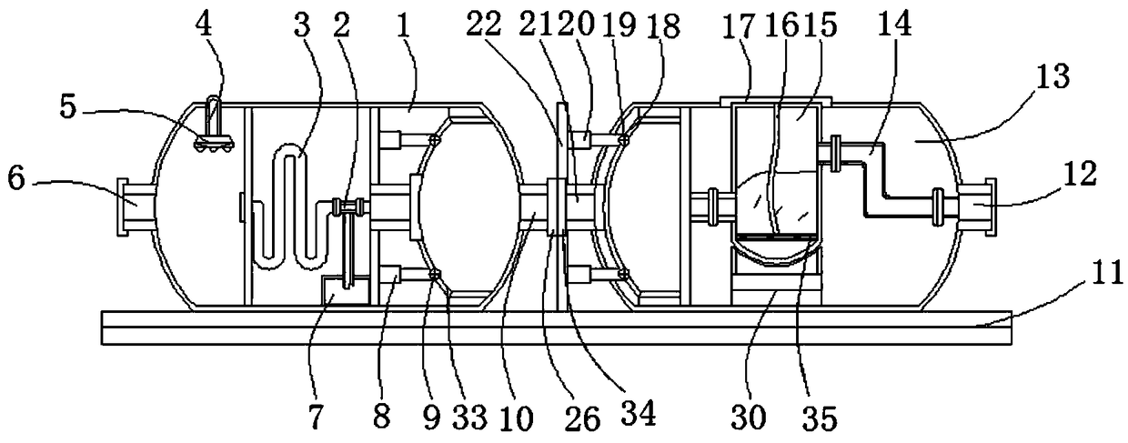
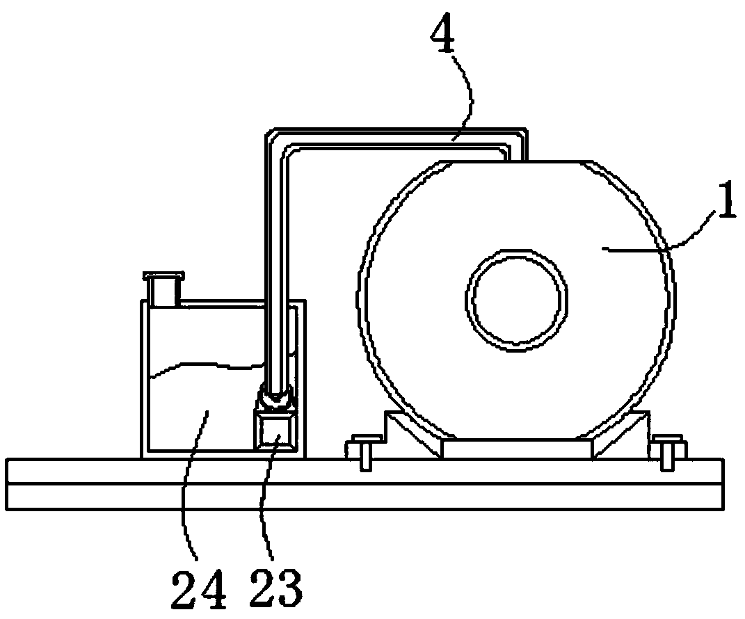
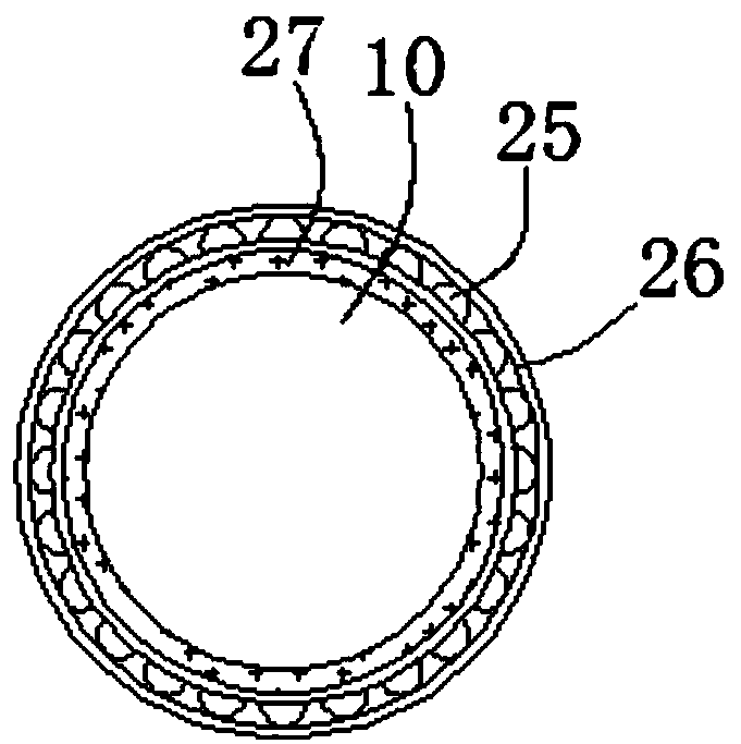
[0027] see Figure 1-5, the present invention provides a technical solution: a high temperature resistant and compressible flue gas desulfurization and denitrification device for coal power plants, including a first main body 1, a return pipe 2, a condensation pipe 3, a connecting pipe 4, a spray head 5, a first Inlet end 6, storage tank 7, first hydraulic rod 8, first pressure sensor 9, first outlet end 10, support plate 11, second outlet end 12, second main ...


PUM


Abstract

The invention relates to a high-temperature-resistant compressible smoke gas desulfurization and denitrification device for a coal electricity plant. The desulfurization and denitrification device comprises a first main body and a filtering disc, wherein a condensing pipe is arranged at the inner side of the first main body; the right side of the condensing pipe is connected with a backflow pipe through screw threads; the left side of the top of the first main body is provided with a connecting pipe in a penetrating way; the bottom end of the connecting pipe is connected with a spraying head.The desulfurization and denitrification device has the beneficial effects that through the arrangement of a first movable bag, a second movable bag, a tube body and a movable cover, the cross sectionradian of the first movable bag is identical to that of the second movable bag; when the device is used for performing pre-compression treatment on smoke gas, a first hydraulic rod is started; the second movable bag is subjected to pushing operation; the region space at the right side inside the first main body is reduced; the pre-compression treatment on the smoke gas is convenient, so that the smoke gas fast enters a second main body; under the combined action of the first movable bag and a second hydraulic rod, compression operation is performed; the desulfurization and denitrification workefficiency of the device on the smoke gas is improved.

Description

technical field [0001] The invention relates to the technical field of flue gas desulfurization and denitrification in coal power plants, in particular to a high temperature resistant and compressible flue gas desulfurization and denitrification device for coal power plants. Background technique [0002] In recent years, the problem of air pollution has become more and more serious. As a large developing country, my country will still face the severe situation of increasing air pollution for a long time to come. The issue of atmospheric pollution control has been attracting great attention all over the world, and it is necessary to desulfurize and denitrify the flue gas through a high-temperature-resistant and compressible flue gas desulfurization and denitrification device. [0003] The existing desulfurization and denitrification devices do not have the function of compressing the flue gas during use, which reduces the working efficiency of the device, and when the device i...

Claims


Application Information

Patent Timeline
Patent Type & Authority Applications(China)
IPC IPC(8): B01D53/75B01D53/79B01D53/86B01D53/48B01D53/56B01D53/26B01D53/04
CPCB01D53/04B01D53/26B01D53/48B01D53/56B01D53/75B01D53/79B01D53/8603B01D53/8625B01D2253/102B01D2258/0283
Inventor 黎丽清
Owner 广州博昊信息科技有限公司
Why Eureka
Try Eureka