Head-mounted display device
A display device and head technology, applied in the direction of optical components, instruments, optics, etc., can solve the problems of shortening the service life of products, falling off, easy to drop products, etc., and achieve the effect of improving reliability and increasing strength
- Summary
- Abstract
- Description
- Claims
- Application Information
AI Technical Summary
Problems solved by technology
Method used
Image
Examples
Embodiment 1
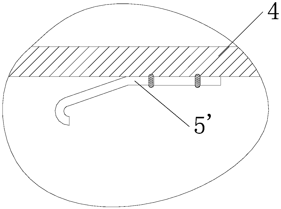
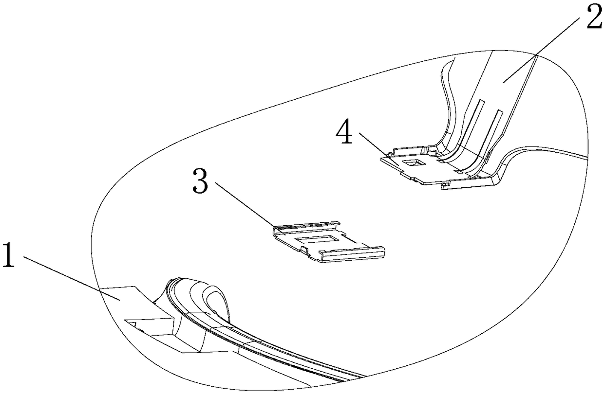
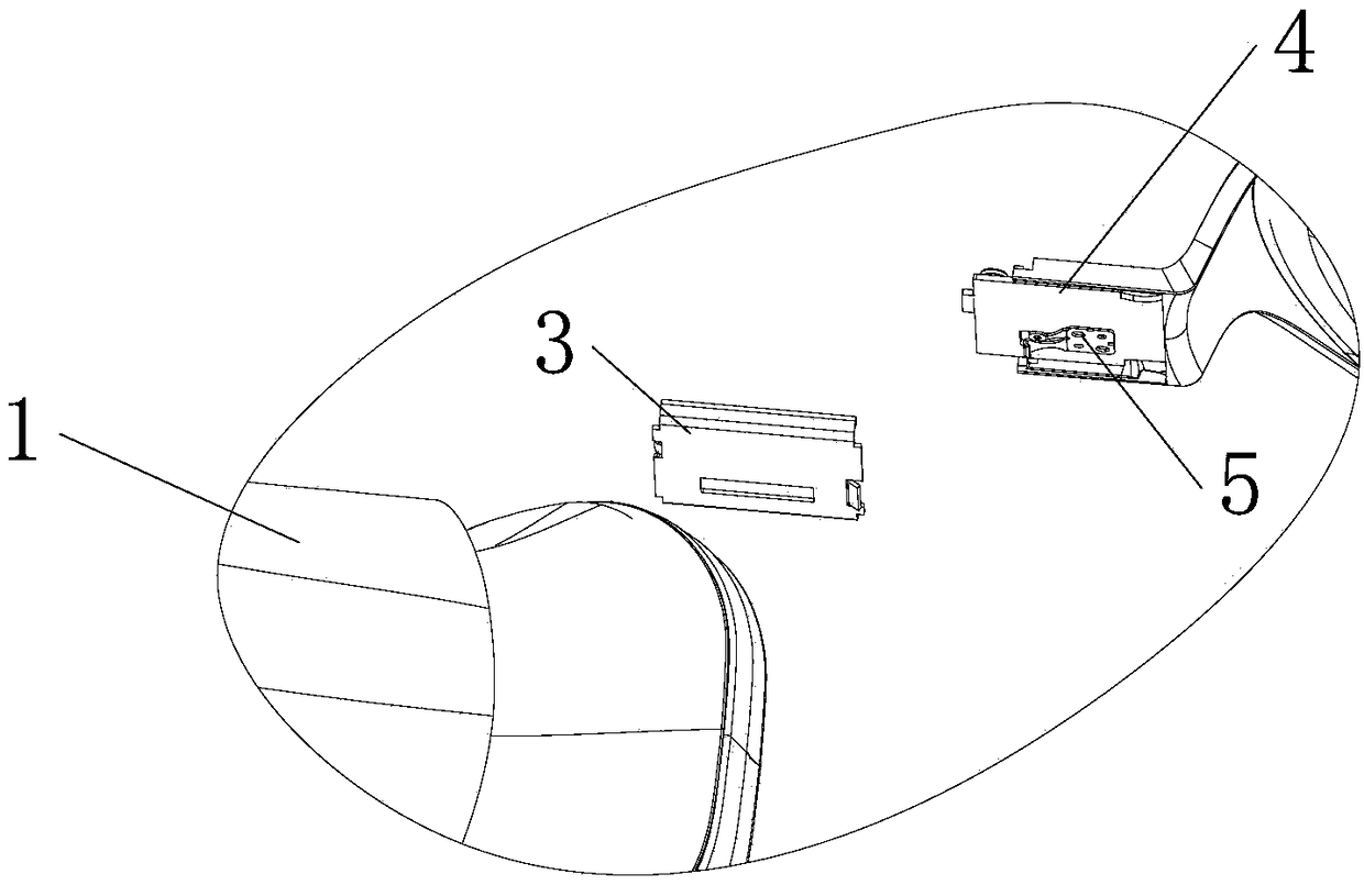
[0035] In order to solve the problem that the hook and the support plate are easy to fall off in the existing head-mounted display device, the present invention provides a head-mounted display device, such as figure 2 and image 3 As shown, it includes a host 1 and a head-mounted assembly 2. The surface of the host 1 is fixedly combined with a connecting portion 3, and the end of the head-mounted assembly 2 is provided with a support plate 4. By plugging and combining the support plate 4 and the connecting portion 3, the host 1 is integrated with the head-mounted assembly 2, so that the host 1 is positioned in front of the user's eyes. In order to prevent the supporting plate 4 from being disengaged from the connecting portion 3 , an anti-loosening device needs to be provided so that the supporting plate 4 and the connecting portion 3 are also in a connected state under the action of an external force. Such as image 3 As shown, the hook 5 is fixed on the bottom surface of ...
Embodiment 2
[0042] Such as Figure 7-11 The connection method between the hook 5 and the support plate 4 in Embodiment 2 of the present invention is shown, and other parts of the head-mounted display device are the same as in Embodiment 1. Such as Figure 7-9 As shown, the fixing part 51 includes a first fixing part 511 and a second fixing part 512 arranged symmetrically, and both the first fixing part 511 and the second fixing part 512 are connected to the tail of the hook 5 . Such as Figure 8 As shown, the first fixing part 511 and the second fixing part 512 are bent in the same direction, as Figure 9 As shown, the first fixing portion 511 and the second fixing portion 512 can also be bent in opposite directions. Such as Figure 10 and Figure 11As shown, the fixing portion 51 includes a first fixing portion 511 , a second fixing portion 512 and a third fixing portion 513 , and the second fixing portion 512 extends in opposite directions to the first fixing portion 511 and the th...
Embodiment 3
[0044] Such as Figure 12-15 The connection mode between the hook 5 and the support plate 4 in Embodiment 3 of the present invention is shown, and other parts of the head-mounted display device are the same as in Embodiment 1. Such as Figure 12 and Figure 13 As shown, a first groove 41 and a second groove 42 are opened in the middle of the support plate 4, the first groove 41 and the second groove 42 are arranged in parallel, and the tail of the hook 5 is formed by bending through the support plate 4 through the first groove 41. The fixing part 51 , the end of the fixing part 51 extends into the second groove 42 and is fixedly connected with the hook 5 . Specifically, the connection can be fixed by welding. Since the solder joints are on the same material, virtual welding caused by different melting points of the materials is avoided and the connection strength is ensured. At the same time, the connection reliability is further improved because the solder joints are hardl...
PUM
 Abstract
Description
Claims
Application Information
 - Generate Ideas
- Intellectual Property
- Life Sciences
- Materials
- Tech Scout
- Unparalleled Data Quality
- Higher Quality Content
- 60% Fewer Hallucinations
Browse by: Latest US Patents, China's latest patents, Technical Efficacy Thesaurus, Application Domain, Technology Topic, Popular Technical Reports.
© 2025 PatSnap. All rights reserved.Legal|Privacy policy|Modern Slavery Act Transparency Statement|Sitemap|About US| Contact US: help@patsnap.com


